Addressing Modes
Last Updated :
14 Feb, 2023
Addressing Modes– The term addressing modes refers to the way in which the operand of an instruction is specified. The addressing mode specifies a rule for interpreting or modifying the address field of the instruction before the operand is actually executed.
Addressing modes for 8086 instructions are divided into two categories:
1) Addressing modes for data
2) Addressing modes for branch
The 8086 memory addressing modes provide flexible access to memory, allowing you to easily access variables, arrays, records, pointers, and other complex data types. The key to good assembly language programming is the proper use of memory addressing modes.
An assembly language program instruction consists of two parts

The memory address of an operand consists of two components:
IMPORTANT TERMS
- Starting address of memory segment.
- Effective address or Offset: An offset is determined by adding any combination of three address elements: displacement, base and index.
- Displacement: It is an 8 bit or 16 bit immediate value given in the instruction.
- Base: Contents of base register, BX or BP.
- Index: Content of index register SI or DI.
According to different ways of specifying an operand by 8086 microprocessor, different addressing modes are used by 8086.
Addressing modes used by 8086 microprocessor are discussed below:
- Implied mode:: In implied addressing the operand is specified in the instruction itself. In this mode the data is 8 bits or 16 bits long and data is the part of instruction.Zero address instruction are designed with implied addressing mode.
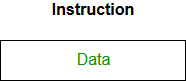
Example: CLC (used to reset Carry flag to 0)
- Immediate addressing mode (symbol #):In this mode data is present in address field of instruction .Designed like one address instruction format.
Note:Limitation in the immediate mode is that the range of constants are restricted by size of address field.
Example: MOV AL, 35H (move the data 35H into AL register)
- Register mode: In register addressing the operand is placed in one of 8 bit or 16 bit general purpose registers. The data is in the register that is specified by the instruction.
Here one register reference is required to access the data.
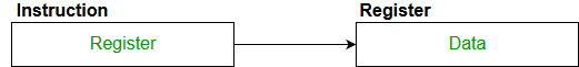
Example: MOV AX,CX (move the contents of CX register to AX register)
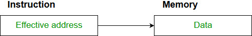
- Register Indirect mode: In this addressing the operand’s offset is placed in any one of the registers BX,BP,SI,DI as specified in the instruction. The effective address of the data is in the base register or an index register that is specified by the instruction.
Here two register reference is required to access the data.

The 8086 CPUs let you access memory indirectly through a register using the register indirect addressing modes.
MOV AX, [BX](move the contents of memory location s
addressed by the register BX to the register AX)
- Auto Indexed (increment mode): Effective address of the operand is the contents of a register specified in the instruction. After accessing the operand, the contents of this register are automatically incremented to point to the next consecutive memory location.(R1)+.
Here one register reference,one memory reference and one ALU operation is required to access the data.
Example:
Add R1, (R2)+  // OR
R1 = R1 +M[R2]
R2 = R2 + d
Useful for stepping through arrays in a loop. R2 – start of array d – size of an element
- Auto indexed ( decrement mode): Effective address of the operand is the contents of a register specified in the instruction. Before accessing the operand, the contents of this register are automatically decremented to point to the previous consecutive memory location. –(R1)
Here one register reference,one memory reference and one ALU operation is required to access the data.
Example:
Add R1,-(R2)   //OR
R2 = R2-d
R1 = R1 + M[R2]
Auto decrement mode is same as auto increment mode. Both can also be used to implement a stack as push and pop . Auto increment and Auto decrement modes are useful for implementing “Last-In-First-Out” data structures.
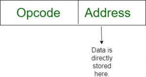
Direct addressing/ Absolute addressing Mode (symbol [ ]): The operand’s offset is given in the instruction as an 8 bit or 16 bit displacement element. In this addressing mode the 16 bit effective address of the data is the part of the instruction.
Here only one memory reference operation is required to access the data.
Example:ADD AL,[0301] //add the contents of offset address 0301 to AL
Indirect addressing Mode (symbol @ or () ):In this mode address field of instruction contains the address of effective address.Here two references are required.
1st reference to get effective address.
2nd reference to access the data.
Based on the availability of Effective address, Indirect mode is of two kind:
- Register Indirect:In this mode effective address is in the register, and corresponding register name will be maintained in the address field of an instruction.
Here one register reference,one memory reference is required to access the data.
- Memory Indirect:In this mode effective address is in the memory, and corresponding memory address will be maintained in the address field of an instruction.
Here two memory reference is required to access the data.
Indexed addressing mode: The operand’s offset is the sum of the content of an index register SI or DI and an 8 bit or 16 bit displacement.
Example:MOV AX, [SI +05]
Based Indexed Addressing: The operand’s offset is sum of the content of a base register BX or BP and an index register SI or DI.
Example: ADD AX, [BX+SI]
Based on Transfer of control, addressing modes are:
Advantages of Addressing Modes
- To give programmers to facilities such as Pointers, counters for loop controls, indexing of data and program relocation.
- To reduce the number bits in the addressing field of the Instruction.
Sample GATE Question
Match each of the high level language statements given on the left hand side with the most natural addressing mode from those listed on the right hand side.
1. A[1] = B[J];         a. Indirect addressing
2. while [*A++];        b. Indexed  addressing
3. int temp = *x;       c. Autoincrement
(A) (1, c), (2, b), (3, a)
(B) (1, a), (2, c), (3, b)
(C) (1, b), (2, c), (3, a)
(D) (1, a), (2, b), (3, c)
Answer: (C)
Explanation:
List 1                           List 2
1) A[1] = B[J];      b) Index addressing
Here indexing is used

2) while [*A++];     c) auto increment
The memory locations are automatically incremented

3) int temp = *x;    a) Indirect addressing
Here temp is assigned the value of int type stored
at the address contained in X
Hence (C) is correct solution.
lease write comments if you find anything incorrect, or you want to share more information about the topic discussed above.
Share your thoughts in the comments
Please Login to comment...