All of the topics covered in the Control System Tutorial, including the Introduction to Control Systems, Classification, Transfer Function, Signal Flow Graphs, Mason Gain Formula, Block Diagram, State Space Model, and more, are included in our tutorial.
The compensator is an extra part that is introduced to the control system’s structure throughout its redesign. It is included in order to make up for the system’s poor performance. A compensator can be mechanical, electrical, hydraulic, or any combination of these.
What is a Compensator?
The word compensation is the root of the compensators. It refers to rearranging a structure’s components to achieve optimal performance. The control system’s feedback mechanism must function properly. Adjustment can occasionally play a significant role in achieving acceptable feedback performance and system improvement. The reason for this is because we frequently need to adjust or modify the system’s parameters.
In these situations, a compensator aids in enhancing the functionality of the control system. Basic and advanced Control System Library ideas are covered in the Control Systems Tutorial. Our Control System Tutorial is appropriate for both novices and experts.
Types of Compensator
- Lead compensator
- Lag compensator
- Lag-lead compensator
Lead Compensator
In a control system, the phase lead is used to produce the output by the lead compensator. Lead in this context refers to ahead. This kind of action is a successor to it.
It is made up of one capacitor C and two resistors, designated R1 and R2.
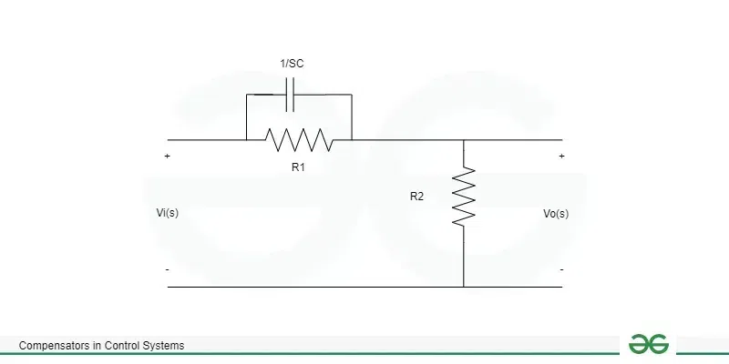
Lead Compensator circuit
The transfer function is defined as the H(s) which is ratio of output voltage to input voltage.
H(s) = Vo(s) / Vi(s)
Here , Vo(s) = R2
The elements in series or parallel configuration (capacitor and resistors) will be the input. The capacitor C1 and resistor R1 are linked in parallel. The resistor R2 is further linked in series with the equivalent parallel combination.
=> R1(1/Cs)/ (R1 + 1/Cs)
The equivalent Vi (s) = R2 + R1(1/Cs)/ (R1 + 1/Cs)
now we know that transfer function H(s) = Vo(s) / Vi(s)
= R2 / [R2 + R1(1/Cs)/ (R1 + 1/Cs)]
= R2(R1Cs + 1) / [R1R2Cs + 1/(R1 + R2)]
= R2/(R1 + R2) (R1Cs + 1) / [R1R2Cs/(R1 + R2) + 1]
Here T = R1 C
A = R2 / (R1 + R2)
H(s) = Vo(s) / Vi(s)
= A (Ts + 1) / (TAs + 1)
Pole = -1/AT
Zero = – 1/T
Phase angle(θ) = sin-1(1 – A / 1 + A)
θ = 90 – 2tan-1(A)1/2
Lag Compensator
In a control system, the lag compensator creates an output that is phase-late. Lag here refers to being behind or delayed. It is made up of one capacitor C and two resistors, designated R1 and R2.
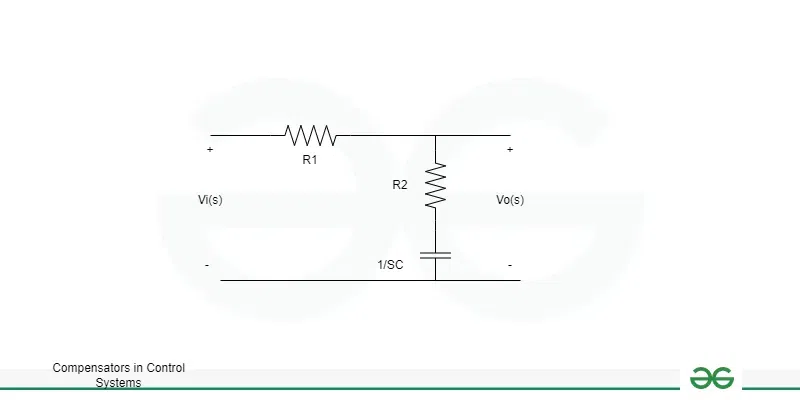
Lag Compensator
An RC circuit is the result of the lag compensator diagram. The output’s connection over the second branch is seen quite clearly. It has a capacitor C linked in series with one resistor R2.
Thus, the circuit’s output is:
Vo(s) = R2 + 1/Cs
Vi(s) = R1 + R2 + 1/Cs
Transfer Function = H(s) = Vo(s) / Vi(s)
= (R2 + 1/Cs ) / (R1 + R2 + 1/ Cs)
= CsR2 + 1 / (Cs(R1 + R2) + 1)
Lets A = R2 + R1
T = R2C
So the required equation will be = H(s) = 1 + Ts / 1 + ATs
Pole = -1 / AT
Zero = – 1 / T
Phase angle (ϕ) = sin-1 [(1 – A) / (1 + A )]
Lag-Lead Compensator
The lag-lead compensator is a mixture of a lag and a lead compensator, as the name suggests.
In a control system, the lag compensator creates an output that is phase-late. In a control system, the phase lead is used to produce the output by the lead compensator. As a result, the output of the lag-lead compensator has phase lead in one frequency area and phase lag in another.
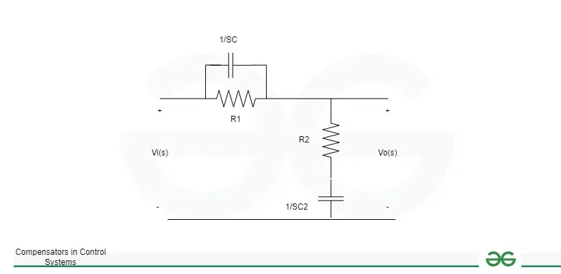
Lag – Lead Compensator
It is made up of two capacitors, C1 and C2, and two resistors, R1 and R2.
Transfer function = H(s) = Vo(s) / Vi(s)
The lag compensator diagram’s output shows that the output is connected across the second branch and is represented as an RC circuit. It has a capacitor, C2, linked in series with one resistor, R2.
Vo(s) = R2 + 1/C2s
Let’s find the input.
It will be:- R2 + 1/C2s
The parallel combination :- R1 x 1/C1s/(R1 + 1/C1s)
The series combination of the combinations mentioned before will now be the comparable input, and it is provided by:
Vi(s) = R2 + 1/C2s + R1 (1/C1s)/(R1 + 1/C1s)
Now the TS will be H(s)
Transfer function H(s) = Vo(s)/Vi(s)
=( R2 + 1/C2s) / {(R2 + 1/C2s) (R1 + 1/C1s) + R1 x 1/C1s}/ ((R1 + 1/C1s)
= (R2 + 1/C2s) (R1 + 1/C1s) / R1R2C1C2s + (R1C1 + R2C2 + R1C2)s + 1
Let, AT1 = R1C1
BT2 = R2C2
T1T2 = R1R2C1C2,
if AB = 1
H(s) = Vo(s)/Vi(s) = (1 + AT1s) (1 + BT2s) / (1 + T1s) (1 + T2s)
Gain Cross over point
The frequency at which the unity gain (zero dB line) and the magnitude response of the system’s open-loop transfer function intersect is known as the crossover point in control systems. This is a critical issue for control system design and stability analysis, especially when considering frequency domain analysis.
In most control systems, changing system parameters like gains, time constants, or the location of poles and zeros will give you control over the crossover point.
Frequency Response Analysis : Analyze the frequency response of the open-loop transfer function. This involves plotting the magnitude and phase response as a function of frequency.
Identify Crossover Point : Locate the frequency at which the magnitude response crosses 0 dB. This is the crossover frequency.
Difference Between Phase Lead and Phase Lag
|
Category
|
Phase lead
|
Phase Lag
|
|
Design
|
Phase angle is added in proximity to the point of gain crossover
|
It keeps the phase margin at the desired level while increasing the error constant.
|
|
Result
|
The enhanced phase shift is caused by an additional phase angle close to the gain crossover point.
It raises the system’s gain at a higher frequency.
|
The gain crossover point is shifted to the lower value.
It lowers the system’s gain. Additionally, it muffles high-frequency noise.
|
|
Advantages
|
A quicker response is the result of the system’s enhanced dynamic response.
It expands the bandwidth of the system.
it functions as a high pass filter
|
By lowering the steady state error, it enhances the system’s steady state performance.
The high-frequency noise is suppressed.
|
|
Disadvantages
|
It requires an additional amplifier gain.
|
It lessens the transitory reaction of the system’s seed.
|
|
Applications
|
It’s employed to quicken the transitory response. Its uses are thus limited to situations requiring a quick transient response.
|
the steady state errors reduced by phase lag
|
Examples
The close loop transfer function is given below. Condition for the transfer function act as the lead compensator
H(s) = K(1 + s/a) / (1 + s/b)
Here Given transfer function given
H(s) = K(1 + s/a) / (1 + s/b)
It is given by:
tan-1 (w/a) – tan-1 (w/b)
For the angle to be positive,
Tan-1w/a should be greater than the tan-1w/b.
Hence, a < b
Find the phase shift provided by the lead compensator of given the transfer function
H(s) = (1 + 6s) / (1 + 2s)
we have H(s) = (1 + 6s) / (1 + 2s)
For the lead compensator H(s) = (s + 1/T) / (s + 1/AT)
A = 1/3
Phase angle (ϕ) = sin-1((1 – A) / ( 1 + A))
= sin-1 ((1-1/3) / (1+1/3))
sin -1 (1/2)
ϕ = 300
Advantages of Compensator
- We are aware that the lead compensator quickens the transient reaction while the lag compensator strengthens the system’s steady-state performance. Therefore, when the system needs to respond quickly and operate in a steady state, the lag-lead compensator is utilized in combination with the other one.
- As we’ve just covered, the lead compensator modifies the transfer function by adding a pole and a dominating zero. Thus, this enhances the system’s total damping.
- Reduced rise and settling times, as well as decreased overshoot, are supported by the system’s improved damping. As a result, the transient reaction is enhanced.
- Phase margin is increased with the installation of lead network.
- Increase the bandwidth.
Disadvantage of Compensator
- A certain amount of attenuation is added to the system with the addition of the lead network. Therefore, there needs to be an additional gain improvement to make up for the attenuation. However, when gain increases, more elements become necessary.
- This results in increased weight and space in addition to increased expense.
- Because the lead network lessens overshoot, undershoot circumstances are increased. The system becomes conditionally stable as a result occasionally.
- A lead angle of roughly 60° is provided by a single lead network. Therefore, a multiple lead compensator needs to be added to the system in order to accommodate the greater lead of around 70 to 90°.
- The lead network expands its bandwidth, but as it does so, the system is more vulnerable to noise.
Applications
- It’s employed to quicken the transitory response. Its uses are thus limited to situations requiring a quick transient response.
- The phase lag reduces the steady state error.
- The control systems are made to carry out particular functions. A control system’s requirements are typically laid out in performance specifications.
- The requirements for response speed, precision, and relative stability.
- A proper compensator should be built when a system’s specifications are provided in order for the system as a whole to meet the requirements.
- Series compensation or parallel feedback compensation are the two types of compensation schemes utilized in feedback control systems.
Conclusion
Control systems have many applications nowadays. These systems are used in industry to regulate the output or operation of other machinery. Various control system types serve various functions. Control systems govern how a machine behaves and operates.
The accuracy and dependability of the equipment and functions control systems may provide make them valuable. Control systems have their origins in both home appliances and industrial.I have just covered the fundamental forms of control systems and how they operate in this tutorial. I’ll be delving deeper into the differences between open loop and closed loop control systems in my upcoming essay.The dynamic field of control engineering is always changing, influencing how we interact with and optimize complex systems. It enables enterprises to attain greater dependability, lower resource consumption, and increased efficiency.
Thus, stay tuned for the forthcoming educational sessions.
FAQs on Compensators in Control Systems
In a control system, what is a compensator?
A compensator is a part or a group of parts that are added to a control system in order to alter its behavior, usually with the purpose of enhancing its robustness, performance, or stability.
Why would someone use a compensator?
A compensator’s main objective is to modify the response of the closed-loop system in order to satisfy performance requirements that include stability margins, steady-state error, and transient response.
Which kinds of compensators are there?
Proportional-integral-derivative (PID) controllers, lead compensators, lag compensators, lead-lag compensators, and state-feedback controllers are examples of common compensator types.
What factors should be taken into account when choosing a compensator?
Stability requirements, performance criteria, robustness to uncertainties and disturbances, complexity, implementation restrictions, and cost-effectiveness are all important factors to take into account.
Share your thoughts in the comments
Please Login to comment...