In this article we will learn about Control Systems – Controllers, The Control systems are an integral part of the various engineering and automation processes. They are responsible for the regulating the behavior of the dynamic systems to achieve desired outcomes. The Controllers are essential components of control systems playing a critical role in maintaining stability and efficiency.
What is Controller?

The controller is a critical component used to regulate the behavior of dynamic system or process. The Controllers are essential for maintaining desired performance and accuracy in various engineering and automation applications. They achieve this by adjusting the input or control signals applied to system based on the feedback or desired setpoints.
The block diagram of controller is a visual representation that illustrates the components and their interactions within control system. It helps in understanding how the controller processes input signals and generates output signals to control a system.
- Input Signal: This represents the signal or reference input that the controller aims to regulate or control. It can be a setpoint or reference signal depending on the specific application.
- Summing Junction : The input signal is compared to actual system output or process variable resulting in calculation of an error signal.
- Controller: The controller block represents the core control algorithm or mechanism responsible for the processing the error signal.
- Control Output: This is the output signal generated by controller in response to the error signal. The control output is used to manipulate the system or process being controlled.
- System or Process: The control output is applied to system or process that needs to be controlled.
- Feedback (Process Variable): Feedback signal often referred to as the process variable is obtained from system or process.
Types of Controllers
The types of controllers are as follows:
- Proportional Controller (P-Controller)
- Derivative Controller (D-Controller)
- Integral Controller (I-Controller)
Proportional Controller (P-Controller)
The proportional controller adjusts the control output in direct proportion to error signal in which is the difference between desired setpoint and the actual process variable.
The Proportional Controller produces an output that is proportional to error signal
The control output (u(t)) is calculated as u(t) = KP * e(t)
where,
KP is the proportional constant.
- The Proportional Controller aims to reduce the error and bring the system closer to setpoint.
- It is effective in reducing steady-state error but may lead to oscillations and overshoot in response.
Advantages
- Simple and easy to implement.
- Provides fast response to errors.
- Reduces steady-state error.
Disadvantages
- Cannot eliminate steady-state error entirely.
- May lead to oscillations or instability in system if not tuned correctly.

The P-controller’s block diagram features a direct connection from input to the controller in which then directly influences the output. The P-controller multiplies the error signal is difference between the desired setpoint and the actual process variable by constant proportional gain (Kp). The resulting control signal is added to system input to correct the error.
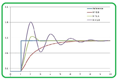
The P-controller reduces the steady-state error but introduces the oscillations and overshoot. It cannot eliminate all error.
Derivative Controller (D-Controller)
The derivative controller reacts to rate of change of the error signal. It anticipates future error trends and provides control action to the counteract them.
The Derivative Controller produces an output that is derivative of the error signal with the respect to time.
The control output is calculated as u(t) = KD * (de(t)/dt)
where,
KD is the derivative constant.
- The Derivative Controller helps in the damping oscillations and improving system stability.
- It is anticipates future errors based on the rate of change of error.
Advantages
- Provides rapid response to the changing errors.
- To Reduces overshoot and oscillations.
Disadvantages
- Amplifies noise and measurement errors.
- Can be sensitive to the parameter variations.

The D-controller’s block diagram features a differentiation block between input and the controller. The D-controller calculates the rate of change of error signal (derivative) and multiplies it by a constant derivative gain (Kd). This derivative term is added to control signal and helping to reduce overshoot and dampen oscillations.
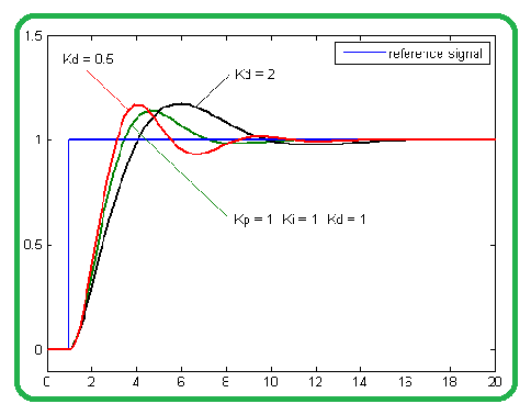
The D-controller improves system stability and transient response reducing overshoot and oscillations.
Integral Controller (I-Controller)
The integral controller responds to cumulative sum of past errors. It continuously adjusts the control output to eliminate any steady-state error.
The Integral Controller produces an output that is the integral of the error signal with respect to time.
The control output is calculated as u(t) = KI * ∫e(t)dt
where,
KI is the integral constant.
- The Integral Controller helps in the eliminating steady-state error by continuously integrating past errors.
- It ensures that the system reaches and maintains setpoint over time.
Advantages
- Eliminates steady-state error completely.
- Increases system accuracy.
Disadvantages
- Slower response to sudden changes in setpoint.
- lead to instability if excessively tuned.

The I-controller’s block diagram features an integration block between input and the controller. The I-controller integrates the error signal over time multiplying it by constant integral gain (Ki). This accumulated error correction is added to control signal and gradually eliminating steady-state errors.
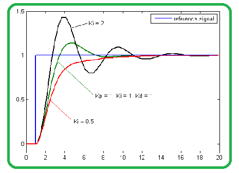
The I-controller eliminates steady-state error but can lead to the slower responses and overshoot if not tuned properly.
Cases in Types of Controllers
Some cases of controllers are :
P-Controller Use Case
Consider a temperature control system in furnace. A P-controller can maintain the desired temperature by adjusting the heating element’s power output. However, it may result in temperature oscillations around the setpoint.
I-Controller Use Case
In a cruise control system for the car an I-controller ensures that the vehicle’s speed remains constant despite changing the external conditions. It eliminates steady-state speed errors.
D-Controller Use Case
In a quadcopter’s stabilization system, a D-controller responds to angular rate errors. It helps maintain a steady and controlled flight by the counteracting sudden changes in the orientation.
Combinations of Controllers
Some of the combinations of controllers are :
Proportional-Derivative (PD) Controller
The PD Controller combines the proportional and derivative controllers.
The control output is u(t) = KP * e(t) + KD * (de(t)/dt).
It improves system stability without the significantly affecting steady-state error.
Proportional-Integral (PI) Controller
The PI Controller combines the proportional and integral controllers.
The control output is u(t) = KP * e(t) + KI * ∫e(t)dt.
It reduces steady-state error while maintaining system stability.
Proportional-Integral-Derivative (PID) Controller
The PID Controller combines the proportional, integral and derivative controllers.
The control output is u(t) = KP * e(t) + KI * ∫e(t)dt + KD * (de(t)/dt).
It provides a balance between reducing steady-state error and damping oscillations.
Applications of Controllers
The Controllers are widely used in various fields:
- Industrial Automation: The Controlling processes in manufacturing and industrial machinery.
- Aerospace: The Managing flight systems, autopilots and navigation.
- Automotive: To Implementing cruise control or anti-lock braking systems and engine control units.
- Robotics: The Regulating robot movements and autonomous navigation.
- Home Automation: The Controlling heating, ventilation and smart devices.
Primary Terminologies of Controllers
- Control System: A system that manages and maintains the behavior of the another system or process.
- Controller: A device or software that regulates the output of the system based on feedback or desired setpoints.
- Plant: The system or process being controlled by controller.
- Setpoint: The desired or target value that the controlled variable should achieve.
- Controlled Variable: The parameter or variable in plant that needs to be controlled.
- Feedback: The process of the continuously monitoring the system’s output and adjusting the control action to maintain the desired performance.
- Open-Loop Control: A control system where the control action is not influenced by the feedback.
- Closed-Loop Control: A control system that uses feedback to adjust the control action is ensuring the controlled variable stays close to setpoint.
Step-by-Step Process of Controllers
The step by step process of controller are:
Define Control Objectives
- Clearly outline the objectives of control system. What is the system intended to achieve or regulate
- To Specify performance criteria such as setpoint values, accuracy and response time.
System Modeling
- Develop a mathematical model of system you intend to control.
- To Create a representation that describes the relationship between the inputs and outputs. This could be a transfer function and state-space representation or a block diagram.
Choose Controller Type
- Select the appropriate type of controller based on system’s characteristics and control objectives.
- The Common controller types include Proportional-Integral-Derivative (PID), Proportional-Integral (PI) and Proportional-Derivative (PD) controllers.
Controller Tuning
- Adjust the controller’s parameters to achieve the desired system response.
- The Tuning may involve manual adjustment, trial and error or automated methods, depending on complexity of the system.
Feedback Loop Design
- Implement a feedback loop that continuously monitors the system’s output and compares it to the desired setpoint.
- The error signal generated from this comparison is used as input to the controller.
Controller Implementation
- Once the controller type and tuning parameters are finalized implement the controller.
- Implementation can be done in the hardware or software.
System Simulation and Testing
- Simulate the control system in controlled environment before deploying it in the real-world applications.
- Test the system’s performance under various scenarios to ensure it meets control objectives.
Iterative Tuning
- After initial testing iterate on controller tuning if necessary.
- The Fine-tune controller parameters such as proportional gain and derivative gain based on the simulation and real-world results.
Real-World Deployment
- Deploy the control system in the actual environment where it will regulate the desired process or system.
- The Continuously monitor its performance during this phase.
Feedback and Optimization
- To Gather data and feedback from control system’s operation in the field.
- The Optimize controller parameters and system settings based on the real-world data.
Maintenance and Upkeep
- The Regularly maintain and service the control system to ensure it operates reliably.
- The Adapt the control system to the changing conditions if necessary to maintain control objectives.
Documentation
- The Maintain comprehensive documentation of control system design including controller parameters and tuning procedures.
Examples of Controller
Cruise Control in Vehicles:

The cruise control is a classic example of a closed-loop control system. The driver sets a desired speed and controller adjusts the throttle or engine power based on feedback from the speed sensors to maintain the set speed.
- Speed Sensor: Measures the actual vehicle speed.
- Reference Speed: Represents the desired speed set by driver.
- Error Calculation: Computes the speed error.
Conclusion
The controllers are indispensable components of control systems that play a pivotal role in regulating and maintaining desired behaviors in the various engineering and industrial processes. Each type of controller, whether proportional, integral or derivative offers distinct advantages and disadvantages is making them suitable for the specific applications. The signal of system or process represents its current state or performance.
FAQs on Controllers
1. What is the difference between open-loop and closed-loop control systems?
The control action is independent of feedback and while in a closed-loop system feedback is used to adjust the control action.
2. What is a PID controller, and how does it work?
A PID controller calculates the control output based on proportional and derivative terms. The eliminate steady-state error and control system response.
3. Can you provide an example of a feedforward control system?
The controller takes action based on predictions and does not rely on feedback. An example is an anti-lock braking system in vehicles which anticipates wheel lockup and adjusts brake pressure.
4. What are some common challenges in controller tuning?
The Controller tuning challenges include achieving stability without oscillations and reducing overshoot.
Share your thoughts in the comments
Please Login to comment...