Compensators, which have a wide range of functionality and variants, are an essential component of Control Systems. The compensator is an electrical system that is used to obtain the desired performance of the system. It is used to stabilize the unstable system. There are various types of compensators such as cascaded, feedback, and cascaded with feedback compensator. Furthermore, the control system is an important subject in the engineering curriculum, and it incorporates many important electronics components. There are some other types of compensators like lead, lag, lag-lead, and lead-lag compensators. The lag compensator eliminates high-frequency noise and improves stability. In this article, we will study lag compensators in detail.
What is a Compensator?
The compensator is a device or component that is used to obtain the desired performance, stability, and behavior of the system. It is the part of the feedback device in a control system and is used to stabilize the system and regulate the other system with its ability of conditioning the input or output form of that system. We can say that is is an electrical network which produces the output in sinusoidal waveform when the sinusoidal input is applied. Basically it means to adjust the frequency response and thus improving the response of the system.

Block Diagram of Compensator
In the above figure R(s) is the input signal, G(s) is the gain in the system, and C(s) is the output signal.
Types of Compensator are as follows:
- Lead Compensator
- Lag Compensator
- Lag-Lead Compensator
- Lead-Lag Compensator
In this topic, we will learn about Lag Compensator.
Lag Compensator
It is an electrical network that produces the sinusoidal output having a phase lag when sinusoidal input is given and it provides the phase lag at the frequencies at the low level thus is reduces the steady state error so we can say that it is meant to produce steady state sinusoidal steady state signal which have the phase lag to the applied input of that system . The effects of lag compensator are as follows:
- Increases the rise time (tr)
- Decreases the peak overshoot (Mp)
- Enhances the stability
- Eliminates the high-frequency noise.
Mathematical Calculation for Lag Compensator
Let us consider the circuit diagram given below for the lag compensator.

Lag Compensator Circuit Diagram
In this diagram, we have two registers R1 & R2, one capacitor which is denoted in Laplace Transform (1/sc), and V0(s) and V1(s) represents the voltage in the circuit. Here, we can see that we are using the capacitor in series with the resistance R2 to obtain the phase lag. The capacitor is the major component responsible for the phase shift, in the lag compensator.
We need to calculate and obtain the transfer function of a certain component or device in a control system, thus we must also calculate the Lag Compensator’s transfer function.
[Tex]Transfer Function = \frac{Output}{Input}[/Tex]
The input voltage V1(s) and current travelling via the first branch where resistor R1 is present, as shown in the lag compensator circuit diagram. The current flowing through the series connection of resistor R2 and a capacitor is then V0(s), and the output voltage is V0(s). The output of the circuit will be:
Output
[Tex]V_{0}(s) = R_{2}+\frac{1}{sc}[/Tex] (due to series connection of resistor and Laplace capacitor 1/sc)
Let us calculate the complete transfer function:
According to the voltage divider rule:
[Tex]V_{0}(s)=\frac{R_{2}+\frac{1}{sc}}{R_{1}+R_{2}+\frac{1}{sc}}V_{i}(s)[/Tex]
[Tex]Transfer function (G(s)) =\frac{1+sR_{2}C}{s(R1+R2)C+1}[/Tex] —- equation(1)
The general transfer function for the compensator is:
[Tex]G_{c}(s)=\frac{s+z}{s+p}[/Tex]
Consider [Tex]p=\frac{z}{\beta}[/Tex]
[Tex]G_{c}(s)=\frac{s+z}{s+\frac{z}{\beta}}[/Tex]
[Tex]G_{c}(s)=\frac{s+\frac{1}{z}}{s+\frac{1}{z\beta}}[/Tex] —- equation(2)
Comparing the equation(1) and equation(2) we will get:
z = R2C
[Tex]\beta=\frac{R1+R2}{R2}[/Tex]
Phase Angle
Since the phase is always negative to calculate the phase angle let us replace ‘s’ with ‘[Tex]j\omega[/Tex]‘ in the equation(2). The transfer function will look like:
[Tex]G_{c}(s)=\frac{j\omega+\frac{1}{z}}{j\omega+\frac{1}{z\beta}}[/Tex]
[Tex]G_{c}(s)=\frac{\beta(1+jz\omega)}{1+jz\omega\beta}[/Tex]
[Tex]Phase Angle= tan^{-1}(z\omega)-tan^{-1}(z\omega\beta)[/Tex]
As we have calculated the value of z and [Tex]\beta[/Tex]:
[Tex]Phase Angle= tan^{-1}(R_{2}C\omega)-tan^{-1}(R_{2}C\omega(\frac{R1+R2}{R2}))[/Tex]
In a transfer function, the numerator is the zeros and the denominators are the poles. The poles and zeros of the equation(1) are:
[Tex]zero=-\frac{1}{R_{2}C}[/Tex]
[Tex]zero=-\frac{1}{(R_{1}+R_{2})C}[/Tex]
The zeros and poles graph in the below image:
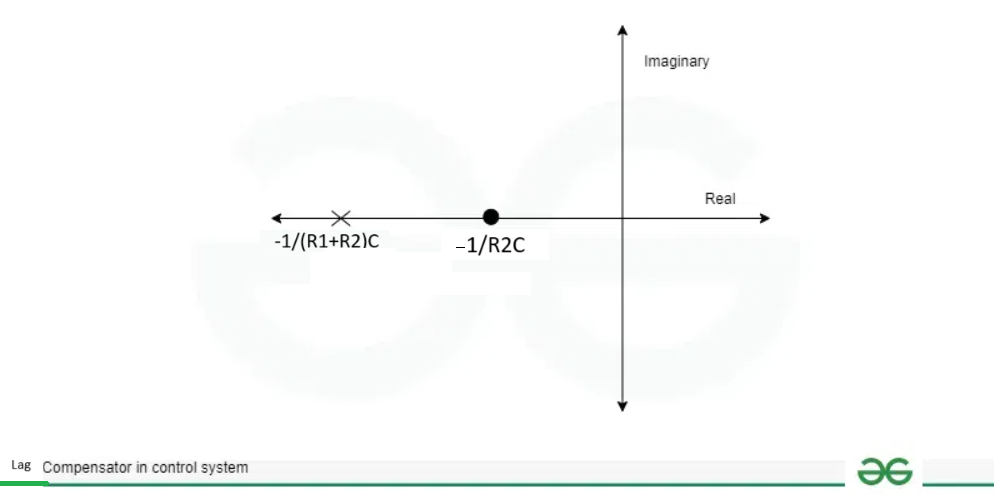
Zeros and Pole of Lag Compensator
Lag Angle
As we have already calculated the phase angle for the lag compensator which is given below:
[Tex]Phase Angle= tan^{-1}(z\omega)-tan^{-1}(z\omega\beta)[/Tex]
[Tex]tan(\phi)=\frac{z\omega-z\omega\beta}{1+z^{2}\omega^{2}\beta}[/Tex] —– equation(1)
Magnitude response will be equal to: [Tex]|G(j\omega)| =\sqrt{\frac{1+z^{2}\omega^{2}}{1+z^{2}\omega^{2}\beta^{2}}}[/Tex]
For the maximum phase condition:
[Tex]\frac{d\phi}{d\omega}|_{\omega=\omega_{m}}=0[/Tex]
[Tex]\omega_{m}=\sqrt{\omega_{c1}\omega_{c2}}=\sqrt{\frac{1}{z}*\frac{1}{z\beta}}[/Tex]
[Tex]\omega_{m}=\frac{1}{z\sqrt{\beta}}[/Tex] —– equation(2)
Substituting the value of [Tex]\omega_{m}[/Tex] in equation(1)
[Tex]tan(\phi)=\frac{1-\beta}{2\sqrt{\beta}}[/Tex]
Magnitude for maximum phase will be:
[Tex]|G(j\omega)|=\frac{1}{\sqrt{\beta}}[/Tex]
The given below shows the bode plot for the phase lag compensator.
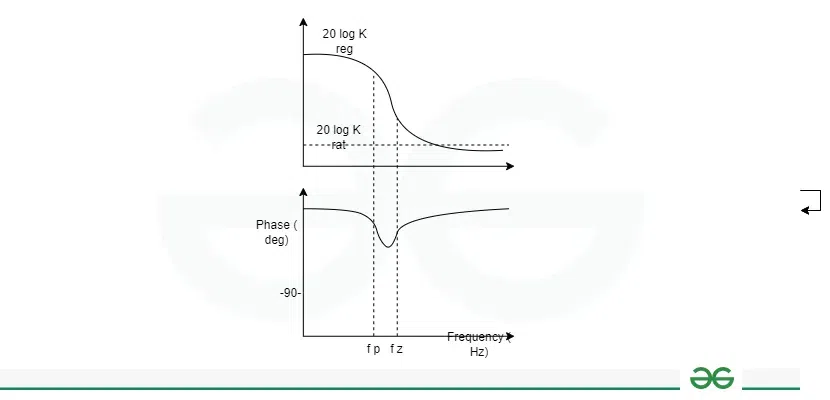
Bode Plot for Lag Compensator
It has two corner frequencies which is shown in above diagram i.e., 1/T and 1/aT (where T=z and a=[Tex]\beta[/Tex]). The phase angle of phase lag compensator is negative which is used to provide the phase lag in the system. It helps in the refining of the transient response of the system which results in reducing the peak overshoot. This results in providing the precise results.
Characteristic of Lag Compensator
- It provides the phase lag to the system which helps in reducing the oscillations. Phase shift helps in adjustment of the phase margin which results in stability enhancement.
- It helps in eliminating the high frequency noise. It has high gain at lower frequencies which helps in greater low frequency correction.
- Similar to to higher frequency noise attenuation, it also attenuates amplitude of the input signals.
- It helps in the refining of the transient response of the system which results in reducing the peak overshoot. This results in providing the precise results.
Advantages and Disadvantages of Lag Compensator
Some of the advantage and disadvantages of the lag compensator are as follows:
Advantages
- It helps in adjusting the phase margin of the system which helps in enhancing the stability.
- It improves the transient response of the system which helps in eliminating the noise and faster settling of the system.
- It helps in the improvement of performance of a system under various disturbances.
- It is easier to implement due to its simple design.
Disadvantages
- It can be applied to low or moderate frequency. It does not provide better results at high frequencies.
- It provides the phase lag to system in order to enhance the stability but on the other side it decreases the gain of the system hence affecting the performance of the system.
- It is sensitive to the external disturbances which can affect the stability.
Applications of Lag Compensator
- It helps in enhancing the stability of the system by introducing the phase lag in the system.
- It adjust the phase margin which is also the another factor for improving the stability of the system.
- It helps in the refining of the transient response of the system which results in reducing the peak overshoot. This results in providing the precise results.
- In order to enhance the stability, precision of the system it is used in robotics, electrical engineering system, and biomedical engineering.
Conclusion
The lag compensator is the important electrical and electronics engineering. It is used to provide the phase lag. As seen in the diagram above, we utilize a capacitor to compensate for phase shift in the compensator. It helps eliminating the high frequency noise and improving the stability of the system. In this article, we have seen the detailed description of the lag compensator, its mathematical calculation in terms of transfer function and phase angle. We have also seen various applications of the same along with its advantages and disadvantages. Due to the above mentioned factors and traits, it has emerged as a key and vital component in electronics and communication engineering.
FAQs on Lag Compensator
What do you mean by the rise time?
Time required for the response to rise from 10% to 90% of the final value for overdamped system at the first instance.
Is the lag compensator used to improve control system stability?
Yes, the lag compensator is used to improve overall stability of a control system, also helps to eliminates the high frequency noise.
What is key difference between a lead and lag compensator?
The lead compensator introduces a phase lead into the system, whereas the lag compensator introduces a phase lag.
Share your thoughts in the comments
Please Login to comment...