In this article, we will discuss about RC circuits. We will discuss the main two elements of the circuit then we will look into the types of RC circuits (series and parallel). We will discuss the power in the series circuit and their equations. We will then look into the step response which includes the forced and natural response. We will also discuss the charging and discharging of the circuit. Later in the article, we will discuss some applications of RC circuits.
What is RC Circuit?
RC Circuit is a special type of circuit that has a resistor and a capacitor. These are two main components of this type of circuit and these can be connected in either series or parallel combinations. this circuit will consume energy because of the presence of a resistor in the circuit. The circuit can be driven by either a voltage source or a current source. The capacitor in the circuit will store energy by charging and discharging which will lead to the change in time behavior of the circuit.
RC Circuit
Resistor
A resistor is a passive element which has two terminals. It restricts the flow of current in circuits. It consume energy and dissipates the energy in the form of heat. Resistance is measured in terms of its characteristics resistance and it is measured in ohms. Resistance is used in Ohm’s law for developing a relation between current and voltage. It used for limiting current and dividing voltage in the circuit.
Resistance is the fundamental property of which opposes the flow of current.
There are many factors that affects the resistance like :
- Different Materials have different resistivity.
- The length of the conductor also affect resistance.
- The cross sectional area of a conductor
[Tex]R=\rho \frac{L}{A} \newline where,\rho\: is\: a\: constant\: called\: resistivity\:
[/Tex]
Capacitor
Capacitor is another passive element it also has two terminals. Its function is to store energy. It is made using of two conductive plates which is separated by a dielectric material. When the current flows through it the electrons get accumulated on the plates and hence energy is stored. It can charge and discharge itself time to time which influences the time behavior of the circuit. It is used in filtering, timing and energy storage in circuits.
Capacitance is the property of capacitor which is measured in farads(F). It stores the energy in electric field. The value of capacitance is dependent on the dielectric material present between the plates.
[Tex]C=\frac{Q}{V}\newline
C=\varepsilon\frac{A}{d}
[/Tex]
Where,
- C is the capacitance .
- Q is the charge stored.
- V is the voltage across the capacitor.
- [Tex]\varepsilon
[/Tex] is the permittivity of the material that is present between the plates.
- A is the surface area.
- d is the separation between the plates.
Types of RC Circuit
Depending on the arrangement of Resistor and Capacitor the circuits can be of two types:
- Series RC Circuits
- Parallel RC Circuits
Series RC Circuits
In this type of circuit, a resistor and capacitor are connected in series.

RC Series Circuit Diagram
In the above diagram,
- I is the RMS value of the current in the circuit.
- VR is the voltage across the resistor R.
- Vc is the voltage across the capacitor.
- V is the RMS value of the supply voltage.
Applying KVL in clockwise direction,
We know, [Tex]V_r=IR\:\:and\:\ V_c=\frac{Q}{C}[/Tex]
Applying KVL,
[Tex]V-V_r-V_c=0
\newline V-IR-\frac{Q}{C}=0[/Tex]
Since Current is same throughout the circuit in series connection we can current as the rate of change of charge with respect to time,[Tex]I=\frac{dQ}{dt}[/Tex]
[Tex]V-R\frac{dQ}{dt}-\frac{Q}{C}=0
\newline\frac{dQ}{dt}+\frac{Q}{RC}=\frac{V}{R}[/Tex]

Phasor diagram
Tha above figure shows the vector diagram,
Steps to draw phasor diagram
- We determine the vector components in the circuit.
- Then we take reference. As the circuit is in series and by the property of series the current I is same throughout so it is taken as reference.
- We have VR=IR as the I and R are in phase with each other. But VR will have lesser magnitude.
- VC=IXC is drawn perpendicular to I as the capacitor is 900 out of phase of each other and is lagging behind.
- The vector sum of the Vc and VR, is given by V and it has an angle of [Tex]\theta[/Tex] which is the power factor angle.
When we take the vector sum we get the following,
[Tex]V^2=V_R^2+V_C^2 \newline
V=\sqrt{V_R^2+V_C^2} \Longrightarrow\sqrt{IR^2+IX_C^2}\newline=I\sqrt{R^2+X_C^2}=IZ
[/Tex]
Z is the impedance of the RC series Circuit,
[Tex]Z=\sqrt{R^2+X_C^2}\newline
where,X_C=\frac{1}{\omega C},{\omega=2\pi f}
[/Tex]
The above figures are the voltage and impedance triangle. From these figures we can see that V lags I by an Angle [Tex]\phi
[/Tex]. So we can write
[Tex]\tan\phi =\frac{IX_C}{IR}
\newline
\phi=\tan^{-1}\frac{X_C}{R}
[/Tex]
So we can say that in a RC series circuit current I leads the voltage V by [Tex]\phi
[/Tex] angle.
Power
[Tex]P=VI\newline
P=(V_m\sin \omega t)(I_m\sin(\omega t+\phi))
\newline=\frac{V_mI_m}{2}[2\sin\omega t* \sin(\omega t+\phi)]
\newline=\frac{V_mI_m}{2}[\cos[\omega t-(\omega t + \phi)]- \cos[\omega t+(\omega t + \phi)]]
\newline=\frac{V_mI_m}{2}[\cos \phi-\cos(2\omega t+ \phi)]
\newline= \frac{V_mI_m}{2}\cos\phi-\frac{V_mI_m}{2}\cos(2\omega t + \phi)
[/Tex]
where , [Tex]\frac{V_mI_m}{2}\cos\phi
[/Tex] is the constant part and [Tex]\frac{V_mI_m}{2}\cos(2\omega t + \phi)
[/Tex] is the variable component.
The average power consumed by the circuit is [Tex]P=VI\cos\phi
[/Tex]
The power factor is [Tex]\cos\phi=\frac{active\: power}{apparent\: power}=\frac{R}{Z}=\frac{R}{\sqrt {R^2+X_C^2}}
[/Tex]
Parallel RC Circuit
In this type of circuit, a resistor and capacitor are connected in parallel combination.

Parallel RC Circuit
In parallel combination the voltage drop across both the elements remains same and using KCL we can say that [Tex]I=I_R+I_C
[/Tex] . Also, [Tex]V=V_R=V_C
[/Tex].
Using the ohm’s law, [Tex]I_R=\frac{V}{R}
[/Tex]
and, [Tex]I_C=C\frac{dV}{dt}
[/Tex].
therefore, [Tex]I=\frac{V}{R}+C\frac{dV}{dt}
[/Tex]
Impedance of the RC parallel circuit is
[Tex]\frac{1}{Z}=\frac{1}{R}+\frac{1}{\frac{1}{j\omega C}}
\newline Z_R=R,Z_C=\frac{1}{j\omega C}
\newline Z= \frac{1}{\frac{1}{R}+j\omega C}=\frac{R}{1+j\omega CR}
\newline Z=\frac{R(1-j\omega CR)}{(1+j\omega CR)(1-j\omega CR)}
\newline Z= \frac{R}{1+\omega^2 C^2R^2}-j\frac{\omega CR^2}{1+\omega^2 C^2R^2}
[/Tex]
the transfer function of the parallel RC circuit is [Tex]\frac{V_{out}}{I}=\frac{R}{1+sRC}
[/Tex]
RC Circuit Current
[Tex]I=\frac{Cs}{1+RCs}V_{in}
[/Tex]
RC Circuit Voltage
Across Capacitor, [Tex]V_C=\frac{1}{1+RCs}V
[/Tex]
Across Resistor, [Tex]V_R=\frac{RCs}{1+RCs}V
[/Tex]
Step Response of RC Circuit
Step response in a circuit is the sudden change of response when the switch closes in the circuit and thus the voltage and current in the circuit also changes. Step response has two parts forced response and natural response. Forced response is the type of response where the supply is turned on. Natural response is the response where the supply is off.
Total step response =Forced Response + Natural Response
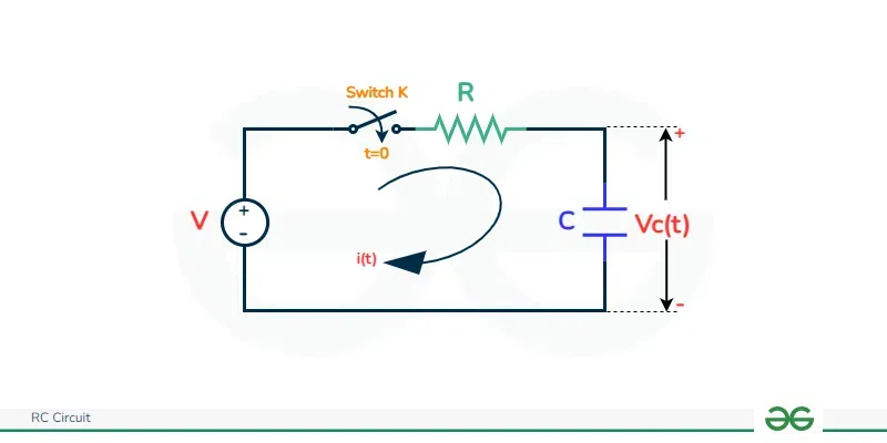
Forced Response
.webp)
Circuit Diagram
In the above figure the circuit is closed at t=0. We apply KCL to the circuit,
[Tex]-Ri(t)-V_C(t)+V_s=0
\newline Ri(t)+V_C(t)=V_s\newline
Current\: through \:capacitor, i_C(t)=C\frac{dV_C(t)}{dt}
\newline substituting, RC\frac{dV_C(t)}{dt}+V_C(t)=V_s
\newline \frac{dV_C(t)}{[V_s-V_C(t)]}=\frac{1}{RC}dt
\newline Integrating\:both\:sides\: we\: get,
-\ln[V_s-V_C(t)]=\frac{t}{RC}+K’
\newline K’\:is\: the\: arbitary\: constant
[/Tex]
We use initial condition and substitute its value to find K’,
[Tex]-\ln[V_s-0]=\frac{0}{RC}+K’
\newline K’=-\ln V_s
[/Tex]
So when we substitute the value of K’ we get,
[Tex]-\ln[V_s-V_C(t)]=\frac{t}{RC}-\ln V_s
\newline \ln \frac{V_s-V_C(t)}{V_s}=-\frac{t}{RC}
\newline Taking\: antilog,
\newline \frac{V_s-V_C(t)}{V_s}=e^{-\frac{t}{RC}}
\newline V_C(t)=V_s(1- e^{-\frac{t}{RC}})
[/Tex]
Natural Response

Circuit Diagram
We apply KVL in the circuit,
[Tex]-Ri(t)-V_C(t)=0
\newline Ri(t)=-V_C(t)\newline
Current\: through \:capacitor, i_C(t)=C\frac{dV_C(t)}{dt}
\newline substituting, RC\frac{dV_C(t)}{dt}=-V_C(t)
\newline \frac{dV_C(t)}{V_C(t)}=-\frac{1}{RC}dt
\newline Integrating\:both\:sides\: we\: get,
\ln[V_C(t)]=-\frac{1}{RC}+K’
\newline K’\:is\: the\: arbitary\: constant
[/Tex]
We use initial condition and substitute its value to find K’ ,
[Tex]\ln[V_0]=-\frac{0}{RC}+K’
\newline K’=\ln V_0
[/Tex]
So when we substitute the value of K’ we get,
[Tex]\ln[V_C(t)]=-\frac{t}{RC}+\ln V_0
\newline \ln \frac{V_C(t)}{V_0}=-\frac{t}{RC}
\newline Taking\: antilog,
\newline \frac{V_C(t)}{V_0}=e^{-\frac{t}{RC}}
\newline V_C(t)=V_0e^{-\frac{t}{RC}}
[/Tex]
Total response = [Tex]V_C(t)=V_s(1-e^{-\frac{t}{RC}})+V_0e^{-\frac{t}{RC}}
\newline V_C(t)=V_s+(V_0-V_s)e^{-\frac{t}{RC}}
[/Tex]
Where, Vs is the step voltage
V0 is the initial voltage on the capacitor.
Time Constant
Time constant is defined as the time required by the resistor and capacitor of a RC circuit to reach its final steady-state value.
[Tex]\tau=RC
[/Tex]
One [Tex]\tau
[/Tex] is the time that is required for the charging the capacitor 63.2% of its final value or discharging the capacitor to 36.8% of its initial value.
Solved Example
Find The time constant of the RC circuit given below

RC Circuit Diagram
Solution:- We know that [Tex]\tau=CR_{eq}[/Tex],
[Tex]\Rightarrow R{eq}=R+\frac{R.R}{R+R}=\frac{3}{2}R[/Tex]
[Tex]\therefore \tau=\frac{3CR}{2}[/Tex]
Find the time constant of the RC circuit when the switch is closed at time t=0?

Circuit Diagram
Solution:-
[Tex]\tau=RC=5k \Omega \:\:X\:\:4mF=20 seconds[/Tex]
RC Circuit Charging

Circuit Diagram for charging
When the current is passed through the capacitor accumulates charge and it charges itself. Initially the capacitor will be uncharged and the voltage across the capacitor will be zero. At t=0+ the voltage will be applied and the voltage across the capacitor will increase. With time the voltage across the capacitor will increase exponentially as per the equation
[Tex]V_C(t)=V(1-e^{-\frac{t}{RC}})
[/Tex]
When substituting it with different values we get the following graph

Charging Voltage Vs Time Relation
RC Charging Table
The voltage across capacitor is given by, [Tex]V_C(t)=V(1-e^{-\frac{t}{RC}})
[/Tex]
Ideally after 4 time constant the capacitor is said to be fully charged and at this point 98% charging has already happened and this point is known as Transient Period. After 5 time constant the capacitor is fully charged, then the current doesn’t flow through the circuit and this is known as steady state period.
The below given table shows the voltage and current percentage at different time constant.
Time Constant
| RC Value
| Percentage of Maximum
Voltage
| Percentage of Maximum
Current
|
|---|
0.5 time constant
| 0.5T-0.5RC
|
39.3%
|
60.7%
|
0.7 time constant
| 0.7T-0.7RC
|
50.3%
|
49.7%
|
1.0 time constant
| 1T-1RC
|
63.2%
|
36.8%
|
2.0 time constant
| 2T-2RC
|
86.5%
|
13.5%
|
3.0 time constant
| 3T-3RC
|
95.0%
|
5.0%
|
4.0 time constant
| 4T-4RC
|
98.2%
|
1.8%
|
5.0 time constant
| 5T-5RC
|
99.3%
|
0.7%
|
RC Circuit Discharging

circuit Diagram for Discharging
When the capacitor is fully charged and the source is disconnected the charge stored in capacitor will remain constant if the voltage across is kept constant. When we replace the source with a short circuit the capacitor will start discharging itself.
[Tex]V_C(t)=V_0e^{-\frac{t}{RC}}
[/Tex]
from this equation we can say that the discharging will also be exponential. When we substitute different values in the equation we will observe the following graph.

Voltage vs Time
Applications
Given below are Some of the Application of the RC circuit
RC High-pass and Low-pass filters
As these circuits take some time for the capacitor to charge and discharge itself they are often used as frequency filters. When the resistor is connected to the voltage source this circuits are knows as low-pass filters. When the configuration is such the capacitor will never fully charge. The capacitor will only low-frequency signals to pass through it while the high frequencies will be stopped from passing.

Low pass circuit
When the capacitor is connected directly to the source then the circuit is known as the high-pass filter. When low frequency signal is passed the reactance of the capacitor becomes high and the voltage drop across the capacitor is more as a result the low-frequency signals are not allowed to pass. Whereas incase of high frequency signals the reactance decreases allowing easy pass of high frequency signals as the capacitor will act like an short circuit.

High Pass circuit
RC coupled Amplifier
It is type of amplifier which is used for audio and low frequency applications. It has multiple stages of amplification that is connected in series and each stage is coupled using a RC Circuit. It is used for transfer of AC output of one stage to the input of the other stage and to reduce the loading effect. It is also used to provide stability to the circuit.

Single stage RC Coupled Amplifier
The input signal is given through Capacitor C1 to the base of transistor. The transistor is configured as common emitter for amplification. The capacitor is used so that it can smoothen the input signal and only allows AC signals. The resistors are used for biasing purpose so that the transistors operate in the active region. The output stage has load resistors and coupling capacitor. The amplified signal is passed through the load resistor for taking the output. The coupling capacitor is used for blocking the DC components for next stage. The frequency response is affected by these circuits the load resistor and coupling capacitor creates a high pass filter and the cutoff frequency depends on the values of resistor and capacitance.
Solved Examples
In the given diagram, a RC series circuit is given with V=12V, C=8[Tex]\mu[/Tex] and R=800[Tex]k\Omega[/Tex]. After the switch is closed, find the time constant, maximum charge on the capacitor, the charge on the capacitor after 6s after switch is closed.

RC Series Circuit Diagram
[Tex]\tau=RC= (500*10^{-3}\Omega)(8*10^{-6})=4 \:seconds[/Tex]
[Tex]Q=Q_f(1-e{\frac{-t}{RC}})
\newline Q_max=CV=(8*10^{-6})(12)=96\mu C[/Tex]
After 6 seconds,[Tex]Q=Q_f(1-e{\frac{-t}{RC}})
\newline =96(1-e^{\frac{-6}{4}})=74.5\mu C[/Tex]
Conclusion
RC circuit is a circuit which contains resistor and capacitor. Capacitor is used for storing the energy and it is used for charging and discharging of the circuit. In this article we looked into the various formula of series and parallel RC circuit. The total step response of RC circuit has two parts forced and natural response. The charging and discharging of this circuit is exponential because of the derived formula. It is used for filter purpose in circuits and also as amplifiers in the circuit.
FAQ on RC Circuit
How RC Circuit can be used as power supply circuits?
RC circuits are not used as primary power supply but it can be used as voltage droppers to reduce the voltage from higher to lower source.
What is reactance and impedance in RC circuits?
Reactance is the characteristics of a capacitor which oppose the flow of alternating current. Impedance is a complex quantity of both resistive and reactive components which opposes the flow of AC in the circuit
What is phasor diagram?
It is a graphical representation of both magnitude and direction of an AC. It shows the phase relationship between two or more sine waves having same frequency.
Share your thoughts in the comments
Please Login to comment...