8051 Microcontroller is a widely used embedded system, that incorporates a robust interrupt system which are important for external communications and real-time applications. Interrupts are the important feature of a microcontroller which enables the microcontroller to respond to the external events and requests, which enhances the multitasking abilities of the microcontroller. An interrupt is an external or internal event/command that interrupts the normal processing of an event and informs the microcontroller that a device needs its service. Whenever a device needs its service, the device sends an interrupt signal to the microcontroller to send a notification. Upon receiving the interrupt signal, the microcontroller stops its existing program and serves the external device request. The program which is associated with the interrupt is known as interrupt Service Routine (IRS) or interrupt handler.
The 8051 features two main types of interrupts, i.e. Hardware interrupts and software interrupts. The hardware interrupts are triggered by external signal such as peripheral events or external devices. The microcontroller can be configured to respond to specific events, allowing for efficient event-driven programming. Whereas, the Software interrupts, are initiated by specific instructions in the program code. They provide a mechanism for the programmer to force the microcontroller to interrupt its normal execution and execute a predefined routine.
The address of the corresponding interrupt service routine (ISR) is included in the suitable interrupt vector associated with every interrupt source in the 8051. The microcontroller automatically maintains its state on interrupt, fetches the interrupt vector’s ISR address, and executes the ISR’s operation. Once the ISR is finished, the microcontroller restarts the task which has been interrupted.
What is an 8051 Microcontroller?
8051 microcontroller is an 8-bit data bus and 16-bit address bus Microcontroller. A 64K (216) byte code memory space and an additional 64K byte data memory space can be addressed using the 16-bit address bus. It has 40 pins and 4K on-chip read only code memory and 128 bytes of internal RAM. It also has various Special Function Registers (SFR) such as the accumulator, the B register, and many other control registers. At a time, the ALU executes an 8-bit operation. It also has two 16-bit counter timers and 3 internal interrupts and 2 external interrupts and four 8 bit I/O ports.
8051 Microcontroller Interrupt
The timer and serial interrupts are internally generated by the microcontroller whereas, the external interrupts are generated by additional peripheral devices or switches that are connected to the microcontroller externally. There are two types of external interrupts: edge-triggered and level-triggered. The interrupt service routine is carried out by the microcontroller as a reaction to an interrupt, enabling memory locations to coincide with interrupts.
Interrupt structure of 8051 Microcontroller
All of the interrupts are disabled by “RESET” thus software is required to enable all of these interrupts. If any one of these five interrupts or all five are activated, the relevant interrupt flags are set. The priority, which is managed by the IP interrupt priority register, determines which of these interrupts can be set or cleared bit by bit in a specific function register that is Interrupt Enabled (IE).
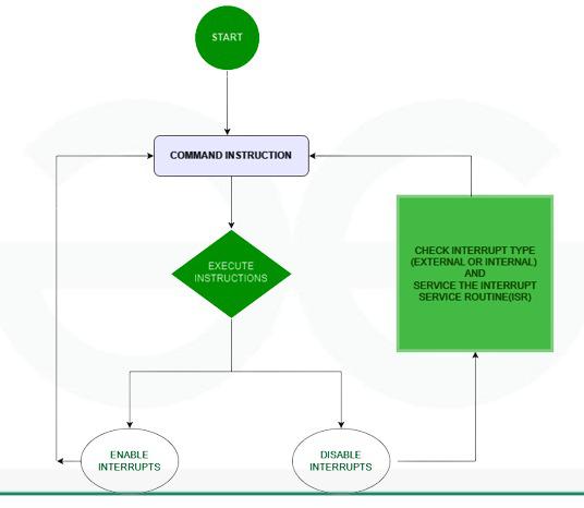
Interrupt handle flowchart.
Two SFRs controls the function of interrupts in 8051 microcontrollers. IE is Responsible for disable/enable the function and IP is Responsible for priority assignment: The priority list offers 3 levels of interrupt priority: Reset: When a reset request arrives, everything is stopped and the microcontroller restarts. Reset can be used to disable the interrupt priority 1. Interrupt priority 0 can be disabled by both Reset and interrupt.
Some of the registers used in this microcontroller are :
- IE (Interrupt Enable) Register
- IP (Interrupt Priority) Register
- TCON (Timer Control) Register
IE (Interrupt Enable) Register
Interrupts can be enabled and disabled using IE Register. It is a register in the 8051 microcontroller that controls interrupt prioritization and triggering. It includes many bits, such as:
EA-Global Interrupt Enable/Disable – When it is set it enables all interrupt, if cleared disables all interrupts
- 0- Disables all interrupt requests
- 1- Enables all interrupt requests
ES (Serial Communication Interrupt Enable)- This bit enables or disables the interrupt for serial communication.
- 1- Interrupt is enabled by UART system
- 0-Interrupt cannot be generated by UART system
ET0- Bit enables or disables timer 0 interrupt.
- 1-Timer 0 is enables an interrupt
- 0-Interrupt cannot be generated by the timer 0
ET1– Bit enables or disables timer 1 interrupt.
- 1- Interrupt is enabled by timer 1
- 0-Interrupt is disabled by timer 1
EX0 and EX1 (External Interrupt 0 and External Interrupt 1 Enable)
- These bits control the interrupts from external devices.
- EX0 – bit enables or disables external 0 interrupt: 0 – change of the INT1 pin logic state cannot generate an interrupt and 1 – enables an external interrupt on the pin INT1 state change.
- EX1 – bit enables or disables external 1 interrupt: 0 – change of the pin INT0 logic state cannot generate an interrupt and 1 – enables an external interrupt on the pin INT0 state change.
IT0 and IT1 (External Interrupt 0 and External Interrupt 1 Type)– These bits determine the type of trigger for external interrupts (level or edge-triggered).

IE (Interrupt Enable) Register
IP (Interrupt Priority) Register
One cannot predict when one may receive an interrupt request. If multiple interrupts are enabled, it can happen that a request for another interrupt is made while the first one is ongoing. There is a priority list that tells the microcontroller what to do in order to determine whether to respond to a new interrupt request or to carry on with existing operations. The microcontroller restarts once everything stops in response to a reset request. Only Reset has the ability to disable Interrupt priority 1. Both Reset and interrupt priority 1 have the ability to disable interrupt priority 0. The interrupt priority register, or IP Register, indicates which of the current interrupt sources is more significant than other. The program’s start typically defines the interrupt priority. An interrupt will be immediately paused and given preference over any other interrupt if the one with greater priority comes while the other is still in progress. Whenever two interrupt requests that have different priorities occurs simultaneously, the higher priority interrupt is handled first. If two interrupt requests with the same priority level arise one after the other, the subsequent request needs to wait until the entire process is accomplished.
Bit0 (PX0)- External0 interrupt priority bit
- 0- Sets low priority to external 0 interrupt
- 1- Sets high priority to external 0 interrupt
Bit1 (PT0)- Timer 0 interrupt priority bit
- 0- Assigns low priority to Timer0 interrupt
- 1- Assigns high priority to Timer0 interrupt
Bit2 (PX1)- External1 interrupt priority bit
- 0- Sets low priority to external1 interrupt
- 1- Sets high priority to external1 interrupt
Bit3 (PT1)- Timer1 interrupt priority bit
- 0- Sets low priority to timer1 interrupt
- 1- Sets high priority to timer1 interrupt
Bit4 (PS)- Serial Input priority bit
- 0- Assigns low priority to serial interrupt
- 1- Assigns high priority to serial interrupt
Bit 5,6 & 7- These bits are called as the Reserved bits.

IP (Interrupt Priority) Register
TCON (Timer Control) Register
The interruptions that the microcontroller interfaces with (external) devices are known as external interrupts. They are received by the controller’s INTx pins. These may be triggered by edges or levels. Interrupt is enabled for a low at the INTx pin when it is level triggered, and for a high to low transition at the INTx pin when it is edge triggered. The TCON register determines whether the triggering is edge or level trigger. The INTx pin for a level trigger interrupt needs to remain low until the interrupt begins and needs to go back to high prior to the interrupt terminating. An interrupt won’t be produced if the low at the INTx pin rises to a high value before the ISR begins. Additionally, the interrupt will be created once more if the INTx pin is low even after the ISR has ended. The level trigger interrupt (low) at the INTx pin must therefore be four machine cycles long, neither longer nor shorter than this.
- IE0- External interrupt 0 edge flag- When an external interrupt edge is detected, hardware sets it. Cleared by the device upon processing the interrupt.
- IE1- External interrupt 1 edge flag-Set by hardware when external interrupt edge is detected. Cleared by hardware when the interrupt is processed.
- TF0- Timer 0 overflow flag-This bit is set whenever timer 0 overflows and is processed by the hardware.
- TF1- Timer 1 overflow flag – This bit is set whenever timer 1 overflows and is processed by the hardware.
- TR0- Timer 0 Run Control- Set this bit to start Timer 0 and clear it to stop the timer. This is important because the timer needs to be running for it to generate interrupts.
- TR1 Timer 1 Run Control – Similar to TR0, this bit controls the running state of Timer 1.
- IT0- Interrupt 0 type control bit- Set/cleared by the device or software to indicate falling edge/low-level triggered external interrupts.
- IT1- Interrupt 1 type control bit- Set/cleared by the device or software to indicate falling edge/low-level triggered external interrupts. Whenever the IT0 and IT1 bits are set, the external interrupts 0 and 1 edge-triggered respectively. These bits are cleared by default, which causes the external interrupt to be level triggered.

TCON (TIMER CONTROL) REGISTER
Types of 8051 Microcontroller Interrupts
8051 Microcontroller suffers five different types of interrupts that hampers the main program execution. These five types of interrupts are:
- Timer 0 overflow interrupt- TF0
- Timer 1 overflow interrupt-TF1
- External hardware interrupt- INT0
- External hardware interrupt- INT1
- Serial communication interrupt- RI/TI
External Hardware Interrupt- (INT0 & INT1)
The 8051 microcontrollers are able to respond to external events through its external interrupts, INT0 and INT1.
External Interrupt 0 (INT0)
- It is connected to the 8051’s pin PORT3.2.
- An interrupt request is issued when this pin transitions from low to high in response to an external signal.
- It is possible to program the microcontroller to carry out a particular Interrupt Service Routine (ISR) in response to this interrupt.
- Set the IE (Interrupt Enable) bit for INT0 in the TCON register and configure the IT0 (Interrupt Type 0) bit in the TCON register corresponding to the desired triggering condition (edge or level-triggered) in order to enable and configure INT0.
External Interrupt 1 (INT1)
- It is connected to the 8051’s pin PORT3.3
- When that particular pin encounters a low-to-high transitions, INT1, like INT0, creates an interrupt request.
- By configuring the IT1 (Interrupt Type 1) bit in the TCON register and setting the IE bit for INT1 in the TCON register, one can enable and configure INT1.
- A specific ISR can be executed by the microcontroller in response to INT1.
Timer Interrupts (Timer0 and Timer1)
Timer 0 and Timer 1 are hardware timers with internal timer interrupts featured in the 8051 microcontrollers. In microcontroller applications, these timers are used to measure time intervals and generate precise delays. The interrupt system of the microcontroller enables it to react quickly to outside events. Interrupts for Timer 0 and Timer 1 are produced when their respective timers exceed their limit. The microcontroller will run the interrupt service routine (ISR) for that timer if the related interrupt is enabled, and the associated interrupt flag is set upon overflow.
Timer0 Interrupt
- Since Timer 0 is an 8-bit timer, its count range is 0 to 255.
- There are two modes of operation for it, 13-bit and 16-bit. It employs the TH0 (Timer 0 High) and TL0 (Timer 0 Low) registers in 13-bit mode and only the TH0 register in 16-bit mode.
- It is possible to set timer 0 to interrupt when it approaches zero instead of staying at its maximum value. The microcontroller can perform a particular interrupt service routine (ISR) in response to the interrupt request that this overflow generates.
Timer1 Interrupt
- Timer 1 is a 16-bit timer with a counting range of 0 to 65,535.
- It can operate in 16- or 8-bit mode. It employs the TL1 (Timer 1 Low) and TH1 (Timer 1 High) registers in 8-bit mode and only the TH1 register in 16-bit mode.
- Timer 1 can be set up to produce an interrupt when it overflows, just like Timer 0. This interruption may cause a certain ISR to be executed.
Serial Communication Interrupts (UART)
UART (Universal Asynchronous Receiver/Transmitter) is a serial communication protocol used with 8051 microcontrollers. Data is sent over a single cable, bit by bit, in serial transmission. In this sense, “interrupts” refers to the processes that enable the microcontroller to react quickly to external events.
Addressing UART communication with the 8051’s interrupts:
- Initialization of UART- Set the data format, baud rate, and enable the UART module by configuring the UART registers.
- Interrupt Enable– Depending on the operation you wish to interrupt for, enable the UART’s transmit interrupt (TI) or receive interrupt (RI).
- ISR (interrupt service routine)- To handle the interrupt, write an ISR. The ISR in UART communication normally verifies whether the transmit buffer is ready (TI) or whether data has been received (RI).
- Clearing the Flag- To recognize the interrupt and get ready for the next one, in the ISR, clear the associated interrupt flag (RI or TI).
Interrupt Vector Table
The addresses of different interrupt service routines (ISRs) are stored in a table called the Interrupt Vector Table (IVT) in an 8051 microcontroller. It is a vital aspect of the interrupt handling mechanism in the microcontroller. When an interrupt occurs the interrupt specific ISR is executed by jumping the program counter to the corresponding address in the IVT. There are memory areas set aside specifically for the IVT in the 8051 microprocessors. Every interrupt has a specific place in the IVT, and the addresses kept there point to the program memory’s associated ISR’s start. By guiding the program flow to the proper place, the IVT enables the microcontroller to respond to external events like hardware interrupts or external signals quickly and effectively.
|
Interrupt
|
Flag
|
Interrupt Vector Address
|
|
Reset
|
–
|
0000H
|
|
INT0 (External Interrupt 0)
|
IE0
|
0003H
|
|
Timer0
|
TF0
|
000BH
|
|
INT1 (External Interrupt 1)
|
IE1
|
0013H
|
|
Timer 1
|
TF1
|
001BH
|
|
Serial Interrupt
|
TI/RI
|
0023H
|
Applications of 8051 Interrupts
- In real-time systems, interrupts are essential for speedy responses to external occurrences. Due to its ability to swap tasks fast through interrupts, the 8051 is a good choice for applications that need exact timing.
- Interrupts serve in the control of incoming data in communication applications, assuring timely transmission or rapid handling of received information.
- In embedded systems, 8051 interrupts are frequently utilized for activities like sensor interfacing, where the microcontroller must react quickly to environmental changes.
- Interruptions assist in ensuring timely data sampling and processing in situations when data must be obtained from sensors or external devices.
- By enabling instantaneous reactions to sensor triggers or alarm situations, interrupts in security systems can ensure prompt alerting and suitable responses.
Solved Examples on 8051 Microcontroller Interrupts
1. Write an 8051 program to enable external interrupts’0’ and ‘1’, configure it to receive edge triggered interrupt request and keep waiting for the interrupt.
ORG 0x00; Start of program memory
MOV P1, #00H; Initialize Port 1
MOV IE, #10001011B; Enable external interrupts (EX0 and EX1)
MOV IT0, #0; Configure INT0 for edge-triggered interrupt
MOV IT1, #0; Configure INT1 for edge-triggered interrupt
MAIN:
NOP; No operation, just wait for interrupts
SJMP MAIN; Jump back to main loop
ORG 0x03; Interrupt Vector for External Interrupt 0 (INT0)
INT0_ISR:
; Your interrupt service routine code for INT0 here
RETI; Return from interrupt
ORG 0x0B; Interrupt Vector for External Interrupt 1 (INT1)
INT1_ISR:
; Your interrupt service routine code for INT1 here
RETI; Return from interrupt
2. Write a program to flash LEDs connected at port 2 With delay of 10 msec. Read data from PORT O continuously and send it to PORT 1 .Use timer 0 in mode 1 with interrupt.
ORG 0000H
LJMP MAIN
ORG 000BH
CLR TCON.4
CLR TCON.5
CPL A
MOV P2,A
MOV THO, # ODB
MOV TLO,# OFF
SETB TCON.4
RETI
MAIN: MOV TMOD,#01h
MOV THO, # ODB
MOV TLO,# OFF
MOV IE, # 82H
MOV A,#00H
MOV P2,#00H
SETB TCON.4
BACK: MOV A, PO
MOV P1,A
SJMP BACK
Advantages of 8051 Microcontroller Interrupt
- By quickly resolving problems, interrupts can be used for error detection and handling, improving the system’s robustness and reliability.
- The 8051’s capability to operate in a low-power mode and wake up only in response to an interrupt helps battery-powered applications operate more energy-efficiently.
- Interrupts make it possible to break up large, complicated processes into smaller, more manageable subroutines, which improves the readability and organization of the code.
- By allowing the microcontroller to be interrupted in response to a predetermined event, the interrupt system minimizes CPU overhead and boosts overall system performance. This eliminates the requirement for constant input polling.
- A few 8051 variations enable interrupt priority levels, which give important tasks the upper hand over less important ones and improve responsiveness and control of the system.
Disadvantages of 8051 Microcontroller Interrupt
- The number of interrupt sources that can be supported is limited by the 8051 microcontroller’s two external interrupt pins (INT0 and INT1).
- The 8051’s interrupt priority cannot be dynamically adjusted; it is fixed. This could render handling several interruption sources with different priorities difficult.
- Variations in the microcontroller’s response time to an interrupt might affect real-time applications where reliable and consistent response times are essential.
- Careful programming is necessary to prevent unexpected behavior while handling interrupts, particularly when working with nested interruptions or crucial portions.
- Since the 8051 lacks vectored interrupts, unlike some other modern microcontrollers, it is required to manually examine interrupt flags in order to identify the interrupt’s source.
Conclusion
The 8051 Microcontroller has the ability to handle interrupts both external as well as internal interrupts. This helps the microcontroller to interface with the external peripherals devices and can be used for real time applications. These interrupts increase the productivity of the microcontroller and can be used for various purposes. interrupts are essential to the operation of 8051 microcontrollers because they give the processor a way to react to outside events quickly and without the need for continuous polling. They improve system efficiency by enabling the microcontroller to manage several tasks at once. Because of their capacity to manage a variety of interrupt sources and prioritize tasks, 8051 microcontrollers provide an adaptable platform for embedded systems, which makes them ideal for applications that demand multitasking and real-time responsiveness. Comprehending and executing interrupt-driven programming efficiently is imperative to fully utilize 8051 microcontrollers in diverse electronic uses.
FAQs on Microcontrollers – 8051 Interrupts
How does 8051 Prioritize interrupt?
The priority in 8051 interrupt is based on their sources. External interrupts have higher priority as compared to internal interrupts like timer and serial and needs to be serviced first.
What is the role of the interrupt Service Routine (ISR) in handling 8051 Interrupt?
The 8051 microcontroller’s ISR (Interrupt Service Routine) deals with particular interrupt occurrences. It facilitates an efficient response to external events by handling context switching, handling the interrupt, clearing flags, updating system state, restoring context, and guaranteeing a smooth return to the main program.
What are the limitations of Vector Address Table?
The fixed size and restricted amount of interrupt vectors of the 8051 microcontroller’s Interrupt Vector Table (IVT) are two of its drawbacks. Only five interrupt sources are usually supported by the original 8051 architecture, and it can be difficult to modify the IVT to support more sources or dynamically alter the vector addresses.
This restriction may be problematic in situations where a system needs more interrupts than what is allotted or where handling interrupts with flexibility is essential. To overcome these constraints, more sophisticated interrupt handling techniques are frequently provided by modern microcontrollers.
Share your thoughts in the comments
Please Login to comment...