A Control System is a system which manages commands and regulates or directs the behaviour of other devices using control loops. A control system is a device which provides the desired response by controlling the output. A control system can also be defined as a system with a combination of mechanical or electronic devices that controls other devices or systems by way of a control loop is called as a control system. The below figure represents the simple block diagram of a control system.

Block diagram of Control System
A signal is a function of one or more independent variables that contain information. In a control system, signals play a crucial role in the analysis and design of the control system to achieve the desired performance and stability. Standard signals are impulse, step, ramp and parabolic. These standard signals are used to know the performance of the control system using the time response of the output. Now let us see the definitions and graphs of time response analysis and frequency response analysis of the control system.
What is a Unit Step Signal?
A unit step signal is also the step signal and one of the standard testing signals. A unit step signal is a specific type of input signal used for analysis, testing and designing. The magnitude of the unit step signal is one. A unit step signal can exist only for positive values and zero for negative values. In other words, let f(t) be a function, then the value of f(t) will be 1 for t>0 (i.e., for positive values of t ) and it will be zero for t<0 (i.e., for negative values of t). It is one of the important signals for the analysis of the systems. Unit step signals can be represented in both continuous and discrete-time systems.
Unit step signal representation in a continuous time system
f(t) = 1 ; for t>=0
f(t) = 0 ; for t<0
The below graph represents the unit step signal in a continuous time system

Graph of Unit Step Signal in Continuous Time System
Unit step signal representation in the discrete-time system
f(n) = 1 ; for n>=0
f(n) = 0 ; for n<0
The below graph represents the unit step signal in a discrete-time system
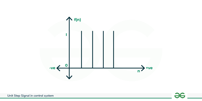
Graph of Unit Step Signal in Discrete Time System
The response of the control systems can be analysed in both time domain and frequency domain. Now let us discuss the time and frequency response analysis of the control system.
Time Response Analysis of the Control System
Time response refers to the behaviour of a system as a function of time when subjected to certain input conditions. Time response examines how a system reacts and evolves after being simultaneously by an input signal. Time response analysis is particularly useful for understanding how quickly a system reaches its final value, how it responds to sudden changes and whether it exhibits oscillatory behaviour.
Time domain response
Frequency Response Analysis of the Control System
Frequency response measures how a system responds to inputs at different frequencies. Frequency response concerns the steady state behaviour of a system under sinusoidal inputs at various frequencies. Frequency response analysis is essential for understanding how a system attenuates or amplifies different frequencies and how phase relationships are affected. It helps in designing a system with specific bandwidth and stability criteria.

Frequency Domain Response
What is a Step Signal?
A step signal is one of the standard testing signals. A step signal is a specific input signal used for analysis, testing and design. A step signal can exist only for positive values and zero for negative values. In other words, let f(t) be a function, then the value of f(t) will be a constant value for t>0 (i.e., for positive values of t) and it will be zero for t<0 (i.e., for negative values of t). It is one of the important signals for the analysis of the systems. Step signals can be represented in both continuous and discrete-time systems.
Step signal representation in a continuous time system
f(t) = a (constant) ; for t>=0
f(t) = 0 ; for t<0
The below graph represents the step signal in a continuous time system

Graph of Step Signal in Continuous Time System
Step signal representation in a discrete-time system
f(n) = a (constant) ; for n>=0
f(n) = 0 ; for n<0
The below graph represents the step signal in a discrete-time system

Graph of Step Signal in Discrete Time System
Types of Unit Step Signal
There are many types of unit step signals. A few of them are discussed below.
- Continuous Time Unit Step Signal
- Discrete-Time Unit Step Signal
- Shifted Unit Step Signal
- Ramp Signal
- Amplified Unit Step Signal
Continuous Time Unit Step Signal
The continuous time unit step is defined below and the graph of it is shown below.
f(t) = 1 ; for t>=0
f(t) = 0 ; for t<0
The below graph represents the unit step signal in a continuous time system

Continuous Time Unit Step Signal
Discrete-Time Unit Step Signal
The discrete-time unit step is defined below and the graph of it is shown below.
f(n) = 1 ; for n>=0
f(n) = 0 ; for n<0
The below graph represents the unit step signal in a discrete-time system

Discrete-Time Unit Step Signal
Shifted Unit Step Signal
This shifted unit step signal is obtained by delaying or advancing the unit step signal in time. For example, u(t-a) is a unit delayed by ‘a’ units or u(t+a) is a unit advanced by ‘a’. The below graphs represent the shifted unit step signal.
.png)
Shifted Unit Step Signal(delayed)
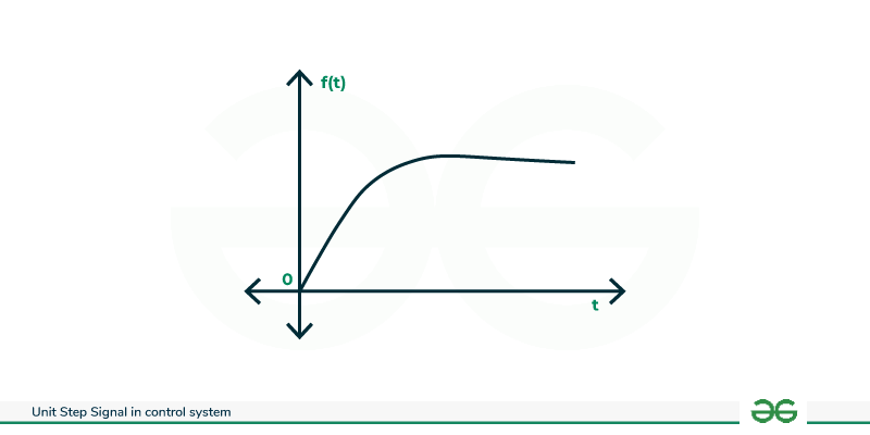
Ramp Signal
signal is represented by r(t). A ramp signal is a continuous or discrete signal that grows linearly with time. In continuous time it is represented as r(t)=t*u(t). The below figure represents the graph of the ramp signal.
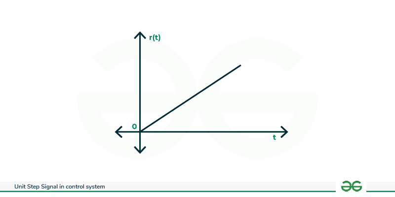
Ramp Signal
Amplified Unit Step Signal
The amplified unit step is represented as in the below expression.
Amplified unit step=A.u(t)
The below graph represents the amplified unit step signal.

Amplified unit step signal
Characteristics of Unit Step Signal
- It exhibits an abrupt change from zero to one at time t=0
- The unit step signal is continuous at t=0, but its derivative experiences an impulse-like behaviour at that point.
- Mathematically, it is often represented using the Heaviside step function, H(t), where u(t)=H(t).
- The derivative of u(t) is often represented by the Dirac delta δ(t).
- Unit step signal exhibits shift property (i.e., u(t-a) or u(t+a)).
- It also exhibits multiplication property (i.e.,u(at) the signal becomes compressed or expanded based on the value of a)
if a>1 : compressed
if 0<a<1 : expanded
- u(t) experience a jump of 1 unit at t=0.
- The unit step signal has a unit area under its curve, meaning the integral of u(t) over the entire range is equal to 1.
- The unit step signal is frequently used in the analysis of linear- time-invariant systems, where it helps describe the system’s response to a sudden change or input.
Different Cases and Relationships of Unit Step Signal
Different signals can be derived from unit step signals some of them are discussed below.
Time Scaling
u(at) is a unit step function. Time scaling does not effect unshifted unit step function. The below equation represents the equation of the time scaling.
i.e., u(at) = u(t)
Proof :
u(at) = 0 ; for at<0 = 0 ; for t<0
u(at) = 1 ; for at>=0 = 1 ; for t>=0
Above equation proved that u(at) i.e., unshifted unit step signal does not effected by Time scaling and is equal to u(t).
Time Shifting
u(t-a)-u(t-b) represents a unit step function between a and b. The below representations are the equations of time shifting.
u(t-a)-u(t-b) =0 ; for t<a
u(t-a)-u(t-b) =1 ; for a<=t<b
u(t-a)-u(t-b) =0 ; for t>=b
Reflection
1-u(t) is a reflected unit step signal. The below-represented equations are the equations of the reflection of the unit step signal.
1-u(t)=1 ; for t<0
1-u(t)=0 ; for t>=0
Applications of Unit Step Signal
- Unit step signal is extensively used to control system analysis.
- It is used for testing and identification of the systems.
- In the signal processing unit step signal is the building block.
- The unit step function is used to represent idealized changes in the system.
- The unit step function is used in the transient analysis of the system.
- It is used in system modelling, PID controller tuning, stability analysis, performance specifications, frequency response analysis and controller design.
Advantages of Unit Step Signal
- The unit step signal has a simple representation.
- Unit step signal provides clear and well-defined changes in the system which makes it useful for testing and analyzing system responses.
- Unit step signal has a versatile nature.
- The unit step signal is a common signal for the control system design.
- Insight into system dynamics.
Disadvantages of Unit Step Signal
- The unit step signal does not capture initial conditions.
- In real-world scenarios, there may be limitations in achieving step-like changes.
- It cannot be used for non-linear systems and it provides limited insights for non-linear systems.
Conclusion
In this Article, We learned What is Unit Step Signal, the types of Unit Steps Signal such as Continuous-time, Discrete-time and others, the characteristics of Unit step signals, and Different cases and relationships such as Time Scaling, Time shifting and Reflection. We have also seen various Applications, Advantages and Disadvantages.
FAQs on Unit Step Signal
Q1. What is a unit step signal?
A step signal is a specific type of input signal used to analysis, testing and designing . A step signal can exists with a magnitude of 1 only for positive values and zero for negative values.
Q2. What is the equation of unit step signal?
f(t) = 1 ; for t>=0
f(t) = 0 ; for t<0
Q3. In how many ways unit step signal is represented? What are they?
Step Signal can be represented two ways Continuous time system and Discrete time system.
Q4. What are the equations of unit step signals in continuous and discrete time systems?
Continuous time system
f(t) = 1 ; for t>=0
f(t) = 0 ; for t<0
Discrete time system
f(n) = 1 ; for n>=0
f(n) = 0 ; for n<0
Share your thoughts in the comments
Please Login to comment...