The transformer is the simplest device that is used to transfer electrical energy from one alternating-current circuit to another circuit or multiple circuits, through the process of electromagnetic induction. A transformer works on the principle of electromagnetic induction to step up or step down voltage. The transformer either increases AC voltage (Step-up transformer) or decreases AC voltage (Step-down transformer).
A transformer which is normally utilized in the transmission and distribution of alternating current power is a voltage control device. Transformers are used for a wide range of purposes, including increasing the voltage from electric generators to enable long-distance transmission of electricity and decreasing the voltage of conventional power circuits to run low-voltage devices like doorbells and toy electric trains.
In this article, we will learn about step-up and step-down transformers and their simulation.
What is a Transformer?
The transformers are passive components that transfer electrical energy from one alternative current source to another circuit. It is also used to boost low voltage to high voltage called step-up transformers as well as reduce high voltage to low voltage called step-down transformers. Transformers works on the principle of Faraday’s law of electromagnetic induction and mutual induction. Based on the conversion, transformers are classified into two types.
Types of Transformers
- Step-Up Transformers
- Step-Down Transformers
The transformers are works under the principle of mutual induction between primary and secondary coil and faraday’s law of electromagnetic induction. Faraday’s law of electromagnetic induction states that, whenever the conductor is placed in a varying magnetic flux, an electro motive force is induced in it.
Mutual induction is the phenomena that amount of magnetic flux linked which changes the Electro Motive Force (EMF) of the neighbor coil.
Parts of Transformers
The important parts of the transformers are primary coil, secondary coil and core.
- Primary coil act a input part of transformer that produces electric flux.
- Core is the important part that helps the linkage of magnetic flux to the neighbor coil.
- Secondary coil act as a output part of the transformer which produce output EMF.

Transformer
Transformer EMF Equation
[Tex]\frac{N_{p}}{N_{s}} = \frac{V_{p}}{V_{s}}
[/Tex] — (1)
- Np refers to number of turns in the primary coil
- Ns refers to number of turns in the secondary coil
- Vp refers to voltage in the primary coil
- Vs refers to voltage in the secondary coil
Now, we are applying the input voltage to the primary coil. The primary coil is linked to the secondary coil that causes EMF in the secondary coil from the primary coil.
Where the primary coil is used for input voltage, the secondary is for output voltage. So, we need to calculate the voltage of the secondary coil.
By rearranging the equation, we get voltage in the secondary coil as:
[Tex]V_{s} = ( \frac{N_{s}}{N_{p}} )*V_{p}
[/Tex] –(2)
A step-up transformer that increases the voltage from the primary winding to the secondary winding. The secondary winding consists of more turns than the primary winding. Step-up transformers are widely used in inverter and booster applications that convert low voltage to the desired high voltage.
Circuit Diagram of Step-Up Transformer
Input AC voltage is applied to the primary winding. Primary winding has fewer turns than secondary winding. Secondary winding acts as an output.

Step-up Transformer
Simulation of Step-Up Transformer
The simulated transformer was constructed with fewer turns in the primary winding than the secondary winding. An input AC voltage is applied to the primary winding. An output EMF is induced at the secondary transformer.
Here, green-colored windings are primary winding, and red-colored windings are secondary winding.

Step-Up Transformer Simulation
Input Parameters for Step-Up Transformer
We can derive the property of a step-up transformer by applying number of turns in secondary coil greater than number of turns in primary coil.
So,
Np < Ns , for step-up transformers
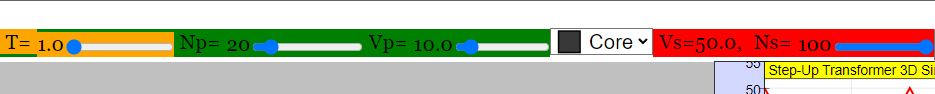
By following the rule of step-up transformer, let’s apply Np = 20 turns and Ns = 100 turns with input AC voltage of 10 volts.
Step-Up Transformer Simulation Result
In the following graph, the green-colored plot refers to the voltage applied at the input primary winding, and the red-colored plot refers to the output voltage obtained at the secondary winding.
The sine wave indicates that the applied current is alternating current (AC).
We are applying 10 volts at the primary winding (Vp = 10 volts). Since it is a step-up transformer, the voltage induced at the secondary winding is 50 volts, according to the calculation given below.

Step-Up Transformer Simulation Graph
Step-Up Transformer Calculation
We know that the voltage in the secondary coil is Vs. By applying the equation (2),
[Tex]{V_{s}} = \frac{N_{s}}{N_{p}}*V_{p}
[/Tex]
When Vp = 10 V , Np = 20, Ns = 100 .[Tex]V_{s} = \frac{100}{20}* 10
[/Tex]Vs = 50 Volts
Step-Up Transformer Result
Here, the applied voltage is 10 volts and the output voltage is 50 volts. Therefore, voltage is increased. Hence, the step-up transformer is proven.
A transformer that decreases the voltage from the primary winding to the secondary winding. Step-down transformers are used to convert high voltage to low voltage. In step-down transformers, the primary winding consists of fewer turns than the secondary winding.
Circuit diagram of Step-Down Transformer
Input AC voltage is applied to the primary winding. Primary winding has more turns than secondary winding. Secondary winding acts as an output.

Step-Down Transformer
Simulation of Step-Down Transformer
The simulated transformer is constructed with a higher number of turns in the primary winding than the secondary winding. An input AC voltage is applied to the primary winding. An output EMF is induced at the secondary transformer.
Here, green-colored winding refers to the primary winding, and red-colored winding refers to the secondary winding.

Step-Down Transformer Simulation
Input Parameters for Step-Down Transformer
We can derive the property of step-down transformer by applying number of turns in the primary coil greater than number of turns in the secondary coil.
So,
Np > Ns , for step-down transformers
By following the rule of step-up transformer, let’s apply Np = 100 turns and Ns = 20 turns with input AC voltage of 10 volts.

Step-Down Transformer Simulation Result
In the graph, the green colored plot refers to the voltage applied at the input primary winding, and the red colored plot refers to the output voltage obtained at the secondary winding.
The sine wave indicates that the applied current is alternating current (AC).
We are applying 10 volts at the primary winding (Vp = 10 volts). Since it is a step-down transformer, the voltage induced at the secondary winding is 2 volts, according to the calculation given below.

Step-Down Transformer Simulation Graph
Step-Down Transformer Calculation
We know that the voltage in the secondary coil is Vs. By applying the equation (2),
[Tex]V_{s} = \frac{N_{s}}{N_{p}}* V_{p}
[/Tex]
When Vp = 10 V , Np = 100, Ns = 20 .[Tex]V_{s} = \frac{100}{20}* 10
[/Tex]Vs = 2 Volts
Step-Down Transformer Result
Here, the applied voltage is 10 volts and the output voltage is 2 volts. Therefore, voltage is decreased. Hence, the step-down transformer is proven.
The following are some of the most common uses for transformer:
- Increasing or reducing the voltage level in an AC circuit to ensure the correct operation of the circuit’s various electrical components.
- It stops DC from flowing from one circuit to another.
- It separates two separate electric circuits.
- Before transmission and distribution can take place, the voltage level at the electric power plant must be increased.
Advantages
- Circuit isolation prevents electric shocks
- Protects circuit from high voltages
- Efficient power transmission
Disadvantages
- Heavy in weight and bulky
- Heat generation
- Energy loss
Conclusion
In this article, we have studied step-up and step-down transformers. It helps in increasing or reducing the voltage level in an AC circuit to ensure the correct operation of the circuit’s various electrical components. Hence, it is an important device in the field of Electrical Engineering.
1. What are the types of transformers based on supply and based on construction?
Transformer based on supply:
- Single phase transformer
- Three phase transformer
Transformer based on construction:
- Core type transformer
- Shell type transformer
2. Why did the core of transformers are laminated?
The core of transformers are laminated to minimize the Eddy Current Loss.
3. Can we apply DC to transformer?
Transformers will not allow DC to flow. Because, EMF cannot be induced without alternating current as per faraday’s law of electromagnetic induction.
Share your thoughts in the comments
Please Login to comment...