NCERT Notes for Class 10 Physics Chapter 12 Electricity is important to study this chapter carefully because it forms the foundation for many other concepts that you will learn later on. Many exam questions will be based on this chapter, so it is essential to have a good understanding of the material.
Chapter 12 of the NCERT Class 10 Physics textbook explores electricity. It covers a variety of topics, including electric current, circuits, power, resistance in series and parallel, and Ohm’s Law. These notes are designed to provide students with a comprehensive summary of the entire chapter and include all of the essential topics, formulas, and concepts necessary for success on exams.
What is Electricity?
A crucial source of energy in today’s society is electricity. It is used in business, transportation, and our homes. For instance, our home’s lighting, fans, and heating systems are all powered by electricity. Electric trains are powered by electricity, which is also used to run a range of devices in industry and in the transportation sector.
The flow of little electrons is what generates electricity. Positive or negative charges can be present in electrons. Negative and negative charges repel one another, while positive and positive charges attract one another.
When two distinct materials are rubbed together, electricity can be produced. For instance, if we brush a silk fabric against a glass rod, the silk cloth will become positively charged and the glass rod would become negatively charged.
Electricity can be used for a variety of purposes, including running equipment, appliances, and lights. It can be used for information transmission and communication as well.
Electric Charge
One coulomb is the amount of electric charge that pushes or pulls with a force of 9 × 10⁹ newtons when another equal charge is placed 1 meter away from it.
The coulomb (C) unit of electric charge. Protons, which are positively charged particles, and electrons, which are negatively charged particles, are present in all matter.
Through contact, friction, or induction, we can move objects close to one another without really touching them to transfer charge from one to the other. The charges will flow from the object with more charge to the object with less charge until they are equal when two objects with different charges are brought together. Static electricity is what we refer to as.
As an illustration, the balloon will become negatively charged if you rub it against your hair, while your hair will become positively charged. Due to the attraction of opposite charges, the balloon will then adhere to your hair.
Note:
- An electron has a negative charge of 1.6 × 10⁻¹⁹ C while a proton has a positive charge of 1.6 × 10⁻¹⁹ C.
- The charge contained in 6.25 × 10¹⁸ electrons is equal to one coulomb (C), the SI unit of electric charge.
Learn more about Electric Charge
Example: Calculate the number of electrons constituting one coulomb of charge.
Solution:
We know that the charge of an electron is 1.6 × 10⁻¹⁹ coulomb (or 1.6 × 10⁻¹⁹ C).
Now, If charge is 1.6 × 10⁻¹⁹ C, No. of electrons = 1
If charge is 1 C, then No. of electrons = 1 / (1.6 × 10⁻¹⁹ C) = 6.25 × 10¹⁸ electron
Electric Current
The movement of electrons via a conductor, such as a wire, is known as electric current. Amperes (A) are units used to measure electric current. The flow of one coulomb of charge per second is equal to one ampere.
For instance, 1 coulomb of charge will flow through a wire if a current of 1 A runs through it for 1 second.
Many items in our homes and workplaces, including lights, appliances, and computers, are powered by electric current.
The magnitude I of the electric current flowing through a conductor if a charge of Q coulombs flows through it in time t seconds is given by:

The letter A stands for an ampere, the SI unit of electric current.
The electric current flowing through a conductor is stated to be 1 ampere when 1 coulomb of charge passes through any cross-section of it in 1 second.

Ammeters are devices that measure current. The circuit in which the current is to be measured and the ammeter are both permanently linked in series
Learn more about Electric Current
Example: An electric bulb draws a current of 0.25 A for 20 minutes. Calculate the amount of electric charge that flows through the circuit.
Solution:
Current, I = 0.25 A
Charge, Q = ? (To be calculated)
And Time, t = 20 minutes
⇒ t = 20 × 60 seconds
⇒ t = 1200 s
Thus, I = Q /t
⇒ Q = It
⇒ Q = 0.25(1200)
⇒ Q = 300 C
Thus, the amount of electric charge that flows through the circuit is 300 coulombs.
Electric Circuit
Electrons can be made to move by a battery, but they require a path to follow. An electrical circuit is a channel that enables electrons to move from a battery to a component, such as a light bulb.
A battery, a conductor, and a gadget are the three main components of a circuit. The battery supplies the energy necessary to move the electrons. The conductor is the channel through which electrons move. A lightbulb is an example of a device, which is something that uses energy from electrons.
Electrons will move from the battery to the device and back to the battery when all of the components of a circuit are connected. A circuit operates in this manner.
Positive and negative terminals are present on batteries. A copper wire connects the positive terminal to the positive end of a light bulb. The opposite end of the light bulb is wired to the negative terminal. In between the two terminals is a switch. A complete circuit is created and current flows through it when the switch is closed. The light bulb is lit by this current.
The circuit is broken when you flip on the switch. This indicates that the current course is no longer complete. The light bulb will stop glowing if the circuit is not complete and the current cannot flow.
Read more about Electric Circuit
Electric Circuit Symbols
Electrical circuits are represented by circuit diagrams. A circuit diagram uses corresponding electrical symbols to represent the relationships between the various electrical components in a circuit.
Electric Potential
When positioned close to a negative charge, a positive charge will feel a pull in that direction. It takes effort to separate the positive charge from the negative charge. The electric potential at a specific place indicates how much effort is needed to transport a positive charge from infinity to that position. The greater your potential, the more work you must put in.
The unit used to measure electrical potential is the volt. The labor is required to move one coulomb of charge one meter is equal to one volt.
Potential Difference
Potential difference is the term used to describe the difference in electric potential between two places. It is the effort required to transfer a unit charge from one location to another.
Alternate names for potential differences include voltage. Current in a circuit is fueled by voltage.
The potential difference V between the two points is given by the formula if W joules of work must be done to transport Q coulombs of charge from one place to the other.

Where,
- W is the work done, and
- Q is the quantity of charge moved.
Volt, represented by the letter V, is the symbol for the potential difference in the SI system. Occasionally, the potential difference is denoted by the symbol p.d.
A device known as a voltmeter is used to measure the potential difference.
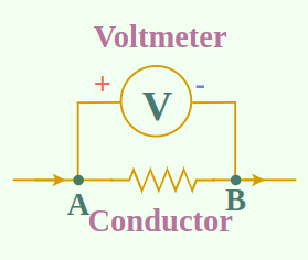
A voltmeter connected in parallel with conductor AB to measure the potential difference across its ends.
Example: How much work is done in moving a charge of 2 coulombs from a point at 118 volts to a point at 128 volts?
Solution:
Q = 2C (coulombs)
Thus, V = 128 – 118
⇒ V = 10 volts
and V = W / Q
⇒ 10 = W / 2
⇒ W = 20 joules
Thus, 20 joules of work is done in moving a charge of 2 coulombs from a point at 118 volts to a point at 128 volts.
Read more about Different between EMF and Potential Difference
Ohm’s Law
Ohm’s law establishes a connection between current and potential differences. At constant temperature, the current flowing through a conductor is precisely proportional to the potential difference across its ends, according to Ohm’s law. If I denotes the current flowing through a conductor and V denotes the potential difference (or voltage) at its ends, then Ohm’s law states:
I ∝ V (At constant temp.)
⇒ V ∝ I
⇒ V = R × I
Where R is the conductor’s “resistance” constant. The value of this constant is determined by the conductor’s type, length, cross-sectional area, and temperature. The equation above can also be written as:

Where,
- V is the Potential difference,
- I is the Current, and
- R is the Resistance (which is a constant).
Example: Potential difference between two points of a wire carrying a 2 ampere current is 0.1 volt. Calculate the resistance between these points.
Solution:
According to the OHM Law, V = R × I
⇒ 0.1 = R × 2
⇒ R = 0.1 / 2
⇒ R = 0.05 ohm
Graph Between V and I
If a straight line is made between the potential difference readings (V) and the related current values (I), the graph is determined to be a straight line flowing through the origin. Only when the two quantities are directly proportionate to one another can a straight-line graph be produced. We get the conclusion that current is exactly proportional to the potential difference because the “current potential difference” graph is a straight line. Graph OA clearly shows that the current I increases along with the potential difference V as V increases, but the ratio of V/I does not change. Resistance of the conductor is the name of this constant.
Resistance of a Conductor
Resistance is the quality of a conductor that causes it to resist the flow of current through it. A conductor’s resistance is equal to the potential difference between its ends divided by the current flowing through it.

Where,
- V is the Potential difference,
- I is the Current, and
- R is the Resistance.
The resistance of a conductor is determined by its length, thickness, material, and temperature. The ohm is the SI unit of resistance, represented by the symbol omega, Ω.
Factor Affecting Resistance
There are various factors that affect the resistance of the conductor,
- Length of the Conductor
- Area of Cross-Section of the Conductor
- Nature of Material of the Conductor
- Temperature
Let’s discuss these effects in detail as follows:
Effect of Length of the Conductor
A conductor’s resistance (R) is proportional to its length (l).
R ∝ l
Effect of Area of Cross-Section of the Conductor
A conductor’s resistance (R) is inversely proportional to its area of cross-section (A).
R ∝ 1/A
Effect of the Nature of Material of the Conductor
A wire’s resistance is determined by the material it is constructed of. While some materials, like copper, facilitate the transmission of electricity, others, like nichrome, do not. The nichrome wire will have roughly 60 times greater resistance than the copper wire if we take two wires of equal length and thickness, but one is made of copper and the other is made of nichrome.
Effect of Temperature
When pure metals are heated, their resistance rises, and when they are cooled, it falls. The reason for this is that when a metal is heated, its atoms move more quickly, which makes it more challenging for electrons to pass through the metal.
The temperature hardly ever has an impact on the resistance of alloys like manganin, constantan, and nichrome. This is a result of the fact that even when heated, the atoms in these alloys find it challenging to move around.
In applications where consistent resistance is necessary, such as in electrical meters and precision instruments, alloys having a low-temperature coefficient of resistance are frequently utilized.
Learn more about Factors Affecting Resistance
Resistivity
As we discussed the effects of various parameters on resistance, let’s derive a formula using all those parameters.
As we know, the resistance (R) of a conductor is proportional to its length (l).
R ∝ l … (1)
and resistance (R) of a conductor is inversely proportional to its area of cross-section (A).
R ∝ 1 / A … (2)
By combining the relations (1) and (2), we get:
R ∝ l / A
⇒ R = (ρI) / A
⇒ ρ = (RA) / I
Where ρ (rho) is a constant known as the resistivity of the material of the conductor. Resistivity is also known as specific resistance.
Example: A copper wire of length 2 m and area of cross-section 1.7 × 10⁻⁶ m2 has a resistance of 2 × 10⁻² ohms. Calculate the resistivity of copper
Solution:
Resistance, R = 2 × 10⁻² ohm
Area of cross-section, A = 1.7 × 10⁻⁶ m2
Length, l = 2 m
⇒ ρ = (2 × 10-2 × 1.7 × 10-6) / 2
⇒ ρ = 1.7 × 10⁻⁸ ohm-meter
Combination of Resistors
The combination of resistors occurs in two ways :
- Resistors in Series
- Resistors in Parallel
Let’s discuss these in detail.
Resistors in Series
If we want to raise overall resistance, we connect the individual resistances in series
Any number of resistances connected in series have a combined resistance that is equal to the sum of the individual resistances. As an illustration, the total resistance R is calculated as follows if several resistances R1, R2, R3,… etc. are connected in series:
R = R1 + R2 + R3 +……
Example: A resistance of 6 ohms is connected in series with another resistance of 4 ohms. A potential difference of 20 volts is applied across the combination. Calculate the current through the circuit.
Solution:
Total resistance,
R = R1 + R2
R = 6 + 4
R = 10 ohms
Now, Total resistance, R = 10 ohms
Potential difference, V = 20 volts
and, Current in the circuit, I = ? (To be calculated)
So, applying Ohm’s law to the whole circuit, we get :
V / I = R
20 / I = 10
I = 2 amperes
Thus, the current flowing through the circuit is 2 amperes.
Resistors in Parallel
if we want to decrease overall resistance, we connect the individual resistances in parallel.
The sum of the reciprocals of all the individual resistances is equal to the reciprocal of the combined resistance of a number of resistances connected in parallel.
For instance, the formula yields the total resistance R if a series of resistances, R1, R2, R3, etc., are connected in parallel.
R = 1/R1 + 1/R2 + 1/R3 + …
Example: Calculate the equivalent resistance when two resistances of 3 ohms and 6 ohms are connected in parallel.
Solution:
1/ R = 1 / R1 + 1 / R2
1 / R = 1 / 3 + 1 / 6
1 / R = (2+1) / 6
1 / R = 3 / 6
R = 2 ohm
Heating Effect of Electric Current
A wire becomes heated when an electric current passes across it. The resistance of the wire and the amount of current flowing through it determines how much heat is generated. When the same amount of current travels through both types of wires, a high-resistance wire, such as a nichrome wire, will heat up more than a low-resistance wire. This is so that greater heat is generated as a result of the high-resistance wire’s increased resistance to the flow of current. The heating effect of electric current is obtained by the transformation of electrical energy into heat energy.
Some of the energy required to push a heavy object is turned into heat as a result of friction. Similarly to this, some electrical energy is turned into heat by resistance when an electric current passes across a wire.
Both friction and resistance act to prevent something from moving. Resistance prevents the flow of electrical current, whereas friction prevents things from moving past one other.
The force and the distance over which it acts determine how much heat is generated by friction or resistance.
Resistance and friction are both unwanted forces, albeit they can serve a purpose. For instance, friction makes it possible for us to walk and drive cars, whereas resistance makes it possible for us to operate electric equipment.
The work done by a current I when it flows through a resistance R for time t. Now, when an electric charge Q moves against a potential difference V, the amount of work done is given by
W = Q × V
According to the OHM Law, V = R × I
and Current ,
⇒ Q = I × t
Thus, W = I × t × R × I
⇒ W = I2Rt
We can substitute “Heat produced” for “Work done” in the equation above if we assume that all electrical work completed or electrical energy used is transformed into heat energy.
W = I2Rt
Example: A potential difference of 250 volts is applied across a resistance of 500 ohms in an electric iron. Calculate the heat energy produced in joules in 10 seconds.
Solution:
Here, Potential difference, V = 250 volts
Current, I = ? (To be calculated)
t = 10 seconds
Resistance, R = 500 ohms
⇒ 250 / I = 500
⇒ I = 1 / 2
⇒ I = 0.5 ampere
The heat energy in joules can be calculated by using the formula : H = I2 × R × t
⇒ H = (0.5)2 × 500 × 10
⇒ H = 1250 joules
Electric Power
The movement of electrons across a conductor is known as electric current. The movement of electrons requires energy. You can perform tasks with the help of this energy, such as heating a stove or lighting a bulb.
Power is the measure of how quickly tasks are completed. Electric power is the rate of depletion of electrical energy.
The watt is the measure of electrical power. One joule of work is equal to one watt of power every second.
A 100-watt light bulb, for instance, consumes 100 joules of energy every second.
P = W / t
The work done W by current I when it flows for time t under a potential difference V is given by :
W = V × I × t
Thus, P = V × I × t / t
And I = Q / t
⇒ Q = I × t
Thus, P = VQ / t
⇒ P = V × I
⇒ P = V2 / R
Example: What will be the current drawn by an electric bulb of 40 W when it is connected to a source of 220 V?
Solution:
P = V × I
Here, Power, P = 40 watts
Voltage, V = 220 volts
And, Current, I = ? (To be calculated)
Now, putting these values in the above formula, we get :
⇒ 40 = 220 × I
⇒ I = 40 / 220
⇒ I = 0.18 ampere
Learn more about Electric Energy and Power
Applications of the Heating Effect of Current
- Electric heating equipment: Many home appliances operate by using the current’s heating impact. Electric irons, kettles, toasters, ovens, room warmers, and water heaters are a few examples of these appliances.
- Electric lightbulbs: The tungsten metal filament inside an electric lightbulb is heated. Due to tungsten’s extremely high melting point, it is able to endure the heat from the current. The filament is heated to a point where it glows and emits light.
- Electric fuses: Electric fuses are safety devices that guard against harm from high currents to residential wiring and electrical appliances. A tiny wire that makes up a fuse melts when a specific current passes across it. By doing so, the circuit is broken and harm to the wiring or appliance is avoided.
Also, Read
FAQs on NCERT Notes for Class 10 Physics Chapter 12 Electricity
Q1: What is an Electric Circuit?
Answer:
A path for electric current to flow is called an electric circuit. It is made up of an electrical energy source, like a battery, a conductor, like a wire, and an electrical energy-using object, like a light bulb.
Q2: What is Electric Current?
Answer:
The passage of electric charge is known as electric current. Amperes (A) are used to measure it.
Q3: What is Voltage?
Answer:
Voltage is the difference in electric potential energy between two points. It is measured in volts (V).
Q4: What is Resistance?
Answer:
The obstacle to the flow of electric current is known as resistance. Ohms (Ω) are used to measure it.
Q5: What is Ohm’s Law?
Answer:
According to Ohm’s law, the current through a conductor is inversely proportional to its resistance and directly proportional to the voltage applied across it.
Q6: What is a Series Circuit?
Answer:
A series circuit is one in which all of the parts are wired together in a single loop. The components are all subject to the same direction of current flow.
Q7: What is a Parallel Circuit?
Answer:
A parallel circuit is a circuit in which the components are connected across each other. The voltage across each component is the same, but the current through each component can be different.
Q8: What is a Combination Circuit?
Answer:
A combination circuit is a circuit that contains both series and parallel components.
Q9: What is Electric Power?
Answer:
The pace at which electrical energy is transformed into other forms of energy, such as heat or light, is known as electric power. Watts (W) are used to measure it.
Share your thoughts in the comments
Please Login to comment...