A conductor has a large number of free electrons. When a potential difference is applied across the ends of a conductor, the free electrons move from one end to the other end of the conductor. When electrons drift or move, they collide with the atoms (ions) of the conductor. These collisions oppose the movement of free electrons from one end to the other end of the conductor. This opposition to the flow of free electrons due to the collisions with ions in a conductor is known as the Resistance of the conductor. The more the collisions suffered by electrons in a conductor, the more is resistance offered by the conductor.
What is the Ohm’s Law?
George Simon Ohm (German Physicist) 1826 studied the relationship between electric current and potential difference across the ends of a conductor. The relation between electric current and the potential difference is known as Ohm’s law.
This law states that the electric current flowing in a conductor is directly proportional to the potential difference across the ends of the conductor, provided the temperature and other physical conditions of the conductor remain the same.
Mathematically, this law can be stated as,
Electric current (I) ∝ Potential difference (V)
⇒ I ∝ V
or
V ∝ I
⇒ V = I × R
where, R is the constant of proportionality and is known as the resistance of the conductor.
Thus, Ohm’s law can be stated as the ratio of potential difference across the end of a conductor to the current flowing through it remains constant if temperature and other physical conditions of the conductor remain the same.
The graph between V and I is a straight line passing through the origin is shown below in the figure:
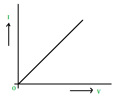
V-I plot
Resistance
In an electrical circuit, resistance is a measure of the resistance to current flow. The Greek letter omega (Ω) is used to represent resistance in ohms. Georg Simon Ohm (1784-1854), a German physicist who investigated the relationship between voltage, current, and resistance, is the name given to Ohms. Ohm’s Law is said to have been formulated by him.
To an extent, all materials resist current flow. They are divided into two groups: Conductors and Insulators.
- Materials with low resistance that allow electrons to travel freely are termed, Conductors.
e.g.: Silver, copper, gold, and aluminum.
- High-resistance materials that prevent electrons from flowing freely are termed Insulators.
e.g.: Rubber, paper, glass, wood, and plastic.
Resistance measurements are commonly used to determine the state of a component or circuit as:
- The lower the current flow, the higher the resistance. Damaged conductors due to burning or corrosion may be one (among many) potential causes if the voltage is abnormally high. Since all conductors emit some heat, overheating is a problem that is often associated with resistance.
- The higher the current output, the lower the resistance. Moisture-damaged insulators or overheating are two possible reasons.
Mathematically, the Resistance of a conductor can be evaluated by using Ohm’s Law as:
According to Ohm’s Law,
V = I × R
Rearrange the above expression for R as,
R = V / I
Hence, the resistance of a conductor is defined as the ratio of the voltage and the current flow through the conductor.
So the unit of the Resistance can be determined as:
R = V / I = 1 Volt (V) / 1 Ampere (A)
= 1 V / 1 A
= 1 Ohm (Ω)
Hence, the unit of resistance is the Ohm (Ω).
Factors that affect the Resistance
Let’s perform an experiment to study the factors on which the resistance of a conductor depends. Connect the various electrical components as shown in the below circuit diagram as:
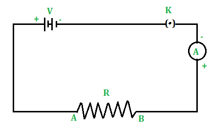
Here, the resistance R is connected through the voltage source V across the ends A and B. The circuit is in ON mode as the key, K is plugged in. Therefore, the current flows in the circuit shown by the Ammeter A. Therefore, the following are the factors on which the resistance of the conductor depends:
1. Length of a Conductor: Consider a Copper wire of length 1 m and connect it between terminals A and B of the circuit. Note the reading of the ammeter. Now take another copper wire of the same area of cross-section but of length 2 m. Connect it between terminals A and B by disconnecting the previous wire. Again, note the reading of the ammeter. It will be found that the reading of the ammeter (i.e., electric current) in the second case is half of the reading of the ammeter in the first case.
- Since I = V / R so the resistance of the second wire is double the resistance of the first wire.
- It shows that the resistance of a conductor is directly proportional to the length of the conductor.
- Thus, more is the length of a conductor, more is its resistance.
2. Area of the cross-section of a Conductor: Now take two copper wires of the same length but of a different area of cross-sections. Let the area of the cross-section of the first wire is more than the area of the cross-section of the second wire. Connect the first wire between terminals A and B in the circuit shown in the figure above. Note the reading of the ammeter. Now disconnect the first wire and connect the second wire between terminals A and B. Again note the reading of the ammeter. It will be found that the reading of the ammeter (i.e., electric current) is more when the first wire (i.e., thick wire) is connected between A and B than the reading of the ammeter when the second wire (i.e., thin wire) is connected between the terminals A and B.
- It shows that the resistance of a conductor is inversely proportional to the area of cross-section of the conductor.
- Thus, the resistance of a thin wire is more than the resistance of a thick wire.
3. Effect of the Nature of material: Take two identical wires, one of copper and the other of Aluminum. Connect the copper wire between terminals A and B. Note the reading of the ammeter. Now, connect the aluminum wire between terminals A and B. Again note the reading of the ammeter. It is found that the reading of the ammeter when the copper wire is connected in the circuit is more than the reading of the ammeter when the aluminum wire is connected in the circuit.
- This implies that the resistance of the copper wire is less than the resistance of the aluminum wire.
- Hence, the resistance of a wire or a conductor depends upon the nature of the material of the conductor.
4. Effect of temperature of the conductor: If the temperature of the conductor connected in the circuit increases, its resistance increases.
Conclusion:
Thus, factors on which resistance of a conductor depends are:
(i) its length (l),
(ii) Area of the cross-section (A),
(iii) the nature of its material and
(iv) its temperature.
Resistivity or Specific Resistance
Experimentally, it is found that the resistance of a conductor is:
- Directly proportional to its length (l) or R ∝ l.
- Inversely proportional to its area of cross-section (A) or R ∝ 1/A.
Let’s combine these two conditions for the resistance as
R ∝ l / A
or
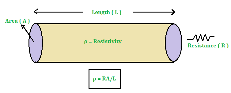
R = ρ × l / A
where ρ is the constant of proportionality and known as the Resistivity or Specific Resistance of the conductor.
Rearrange the above expression for ρ,
ρ = R × A / l
- Thus, the Resistivity of a conductor is defined as the resistance of the conductor of unit length and unit area of cross-section.
- In other words, the resistivity of the conductor is termed as the resistance offered by 4 cubical conductors of 1 m side to the flow of current across the opposite face of the conductor.
- In CGS system the unit of resistivity or specific resistance is ohm-cm (Ω-cm).
- In SI unit of resistivity or specific resistance is ohm-meter (Ω-m).
To understand more about the concept and formula of resistivity let’s consider an example as:
Example: A conductor having a resistance of 20 Ohms is drawn out so that its length is increased to twice its original length. Calculate the resistance of the new wire.
Solution:
Given that,
The resistance of the conductor, R is 20 Ω.
If original length of the conductor is l then new length (l’) of the conductor is 2l.
So, if the original cross-sectional area is A and new cross-sectional area is A’, then:
Since, l’ = 2l therefore A’ = A / 2.
In case of the original conductor, original resistance is:
R = ρ × l / A
20 Ω = ρ × l / A …… (1)
Now, in case of the new conductor, new resistance is:
R’ = ρ × l’ / A’
= (ρ × 2l) / (A / 2)
= (4 × ρ × l) / A
Use equation (1) in the above expression and solve to calculate R’.
R’ = 4 × 20 Ω
= 80 Ω
Hence, the resistance of the new wire is 80 Ω.
Sample Problems
Problem 1: Find the resistance of a conductor if the current flowing through it is 0.3 A and the applied potential difference is 0.9 Volts.
Solution:
Given that,
The current flow, I is 0.3 A.
The applied potential difference, V is 0.9 V.
Now, use the formula:
R = V / I
= 0.9 V / 0.3 A
= 3 Ω
Hence, the resistance of a conductor is 3 Ω.
Problem 2: A heater has a resistance of 50 Ω and connected to a 220 Volt supply, calculate the current in the heater.
Solution:
Given that,
The resistance of the heater, R is 50 Ω.
The potential difference, V is 220 V.
Now, use the formula:
V = I × R
Rearrange the above expression for I as,
I = V / R
= 220 V / 50 Ω
= 4.4 A
Hence, the current in the heater is 4.4 A.
Problem 3: The resistivity of iron and mercury is given by 10.0 x 10⁻⁸ and 94 x 10-8 Ω.cm respectively. Which one is the better conductor?
Solution:
A material whose resistivity is low is consider as good conductor of electricity.
Hence, Iron is the good conductor than Mercury.
Problem 4: Define 1-Ohm resistance.
Solution:
Resistance of a conductor is said to be 1 ohm if a potential difference of 1 volt across the ends of the conductor makes a current of 1 ampere to pass through it.
Problem 5: Let the resistance of an electrical component remains constant while the potential difference across the ends of the components decreases to half of its former value. What change will occur with current through it?
Solution:
Since, I = V / R, when V’=V / 2
I’ = V / 2R = I / 2
Thus, the current in the components becomes half of its former value.
Share your thoughts in the comments
Please Login to comment...