Counters in Digital Logic
Last Updated :
06 Mar, 2023
A Counter is a device which stores (and sometimes displays) the number of times a particular event or process has occurred, often in relationship to a clock signal. Counters are used in digital electronics for counting purpose, they can count specific event happening in the circuit. For example, in UP counter a counter increases count for every rising edge of clock. Not only counting, a counter can follow the certain sequence based on our design like any random sequence 0,1,3,2… .They can also be designed with the help of flip flops. They are used as frequency dividers where the frequency of given pulse waveform is divided. Counters are sequential circuit that count the number of pulses can be either in binary code or BCD form. The main properties of a counter are timing , sequencing , and counting. Counter works in two modes
Up counter
Down counter
Counter Classification
Counters are broadly divided into two categories
- Asynchronous counter
- Synchronous counter
1. Asynchronous Counter
In asynchronous counter we don’t use universal clock, only first flip flop is driven by main clock and the clock input of rest of the following flip flop is driven by output of previous flip flops. We can understand it by following diagram-
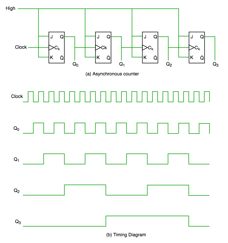
It is evident from timing diagram that Q0 is changing as soon as the rising edge of clock pulse is encountered, Q1 is changing when rising edge of Q0 is encountered(because Q0 is like clock pulse for second flip flop) and so on. In this way ripples are generated through Q0,Q1,Q2,Q3 hence it is also called RIPPLE counter and serial counter. A ripple counter is a cascaded arrangement of flip flops where the output of one flip flop drives the clock input of the following flip flop
2. Synchronous Counter
Unlike the asynchronous counter, synchronous counter has one global clock which drives each flip flop so output changes in parallel. The one advantage of synchronous counter over asynchronous counter is, it can operate on higher frequency than asynchronous counter as it does not have cumulative delay because of same clock is given to each flip flop. It is also called as parallel counter.
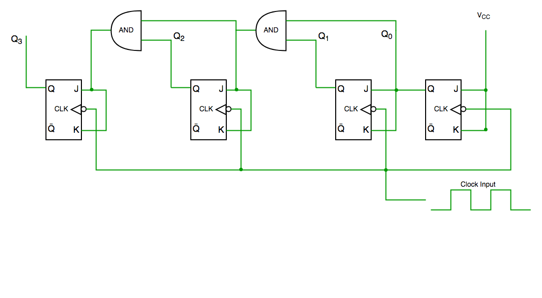
Synchronous counter circuit

Timing diagram synchronous counter
From circuit diagram we see that Q0 bit gives response to each falling edge of clock while Q1 is dependent on Q0, Q2 is dependent on Q1 and Q0 , Q3 is dependent on Q2,Q1 and Q0.
Decade Counter
A decade counter counts ten different states and then reset to its initial states. A simple decade counter will count from 0 to 9 but we can also make the decade counters which can go through any ten states between 0 to 15(for 4 bit counter).
| Clock pulse |
Q3 |
Q2 |
Q1 |
Q0 |
| 0 |
0 |
0 |
0 |
0 |
| 1 |
0 |
0 |
0 |
1 |
| 2 |
0 |
0 |
1 |
0 |
| 3 |
0 |
0 |
1 |
1 |
| 4 |
0 |
1 |
0 |
0 |
| 5 |
0 |
1 |
0 |
1 |
| 6 |
0 |
1 |
1 |
0 |
| 7 |
0 |
1 |
1 |
1 |
| 8 |
1 |
0 |
0 |
0 |
| 9 |
1 |
0 |
0 |
1 |
| 10 |
0 |
0 |
0 |
0 |
Truth table for simple decade counter
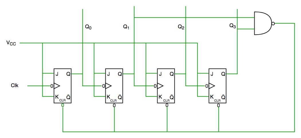
Decade counter circuit diagram
We see from circuit diagram that we have used nand gate for Q3 and Q1 and feeding this to clear input line because binary representation of 10 is—
1010
And we see Q3 and Q1 are 1 here, if we give NAND of these two bits to clear input then counter will be clear at 10 and again start from beginning.
Important point: Number of flip flops used in counter are always greater than equal to (log2 n) where n=number of states in counter.
Some previous years gate questions on Counters
Q1. Consider the partial implementation of a 2-bit counter using T flip-flops following the sequence 0-2-3-1-0, as shown below
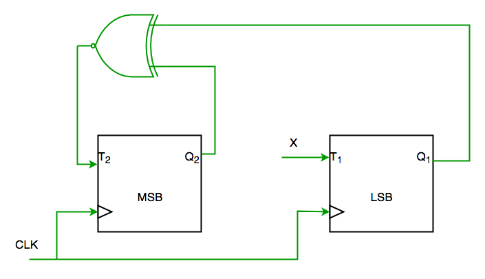
To complete the circuit, the input X should be
(A) Q2?
(B) Q2 + Q1
(C) (Q1 ? Q2)’
(D) Q1 ? Q2 (GATE-CS-2004)
Solution:
From circuit we see
T1=XQ1’+X’Q1—-(1)
AND
T2=(Q2 ? Q1)’—-(2)
AND DESIRED OUTPUT IS 00->10->11->01->00
SO X SHOULD BE Q1Q2’+Q1’Q2 SATISFYING 1 AND 2.
SO ANS IS (D) PART.
Q2. The control signal functions of a 4-bit binary counter are given below (where X is “don’t care”)
The counter is connected as follows:
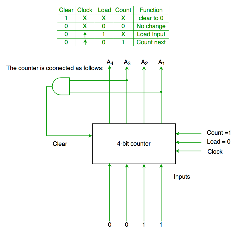
Assume that the counter and gate delays are negligible. If the counter starts at 0, then it cycles through the following sequence:
(A) 0,3,4
(B) 0,3,4,5
(C) 0,1,2,3,4
(D) 0,1,2,3,4,5 (GATE-CS-2007)
Solution:
Initially A1 A2 A3 A4 =0000
Clr=A1 and A3
So when A1 and A3 both are 1 it again goes to 0000
Hence 0000(init.) -> 0001(A1 and A3=0)->0010 (A1 and A3=0) -> 0011(A1 and A3=0) -> 0100 (A1 and A3=1)[ clear condition satisfied] ->0000(init.) so it goes through 0->1->2->3->4
Ans is (C) part.
Quiz on Digital Logic
Article contributed by Anuj Batham,
Share your thoughts in the comments
Please Login to comment...