Digital Logic & Number representation
Question 1
What is the minimal form of the Karnaugh map shown below? Assume that X denotes a don’t care term.
[caption width="800"].png) [/caption]
[/caption]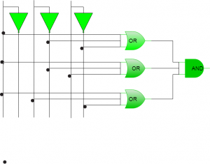 The value of F is:
Question 3
A binary 3-bit down counter uses J-K flip-flops, FFi with inputs Ji, Ki and outputs Qi, i = 0, 1, 2 respectively. The minimized expression for the input from following, is 

Question 5
In the following truth table, V = 1 if and only if the input is valid.
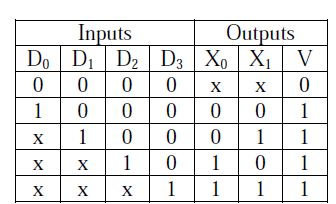 What function does the truth table represent?
 What function does the truth table represent?
Question 6
Which one of the following expressions does NOT represent exclusive NOR of x and y?
Question 7
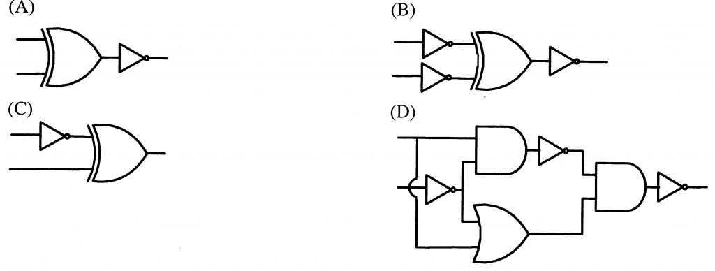
Which one of the following circuits is NOT equivalent to a 2-input XNOR (exclusive NOR) gate?

Question 8
The simplified SOP (Sum Of Product) form of the boolean expression (P + Q\' + R\') . (P + Q\' + R) . (P + Q + R\') is
Question 9
Consider the following circuit involving three D-type flip-flops used in a certain type of counter configuration.
[caption width="800"]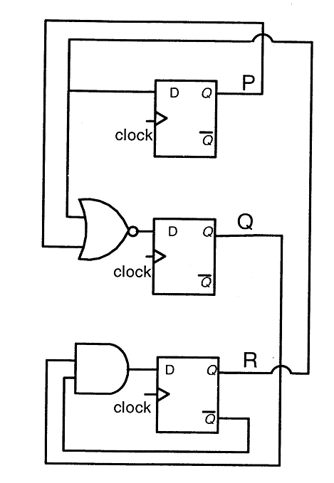 [/caption]
If at some instance prior to the occurrence of the clock edge, P, Q and R have a value 0, 1 and 0 respectively, what shall be the value of PQR after the clock edge?
Question 10
Consider the data given in previous question. If all the flip-flops were reset to 0 at power on, what is the total number of distinct outputs (states) represented by PQR generated by the counter?
There are 264 questions to complete.
Last Updated :
Take a part in the ongoing discussion