Image and video processing is the primary application of OpenCV. Images are captured by cameras, which use lenses to convert 3D objects from the real world into 2D images. However, because lenses are used during the transformation, some distortions are also introduced to the pictures. In order to prevent capturing distorted images, the camera needs to be calibrated, to accurately relate a 3D point in the real world to its matching 2D projection (pixel) in the image. Hence, camera calibration means determining the parameters of the camera to capture an undistorted image which is carried out by the function calibrateCamera() in Opencv.
The object in the real world exists in the World Coordinate System (3D) which when captured by the camera is viewed in Camera Coordinate System (3D). Finally, to project the captured image, the result is viewed in Image Coordinate System (2D).
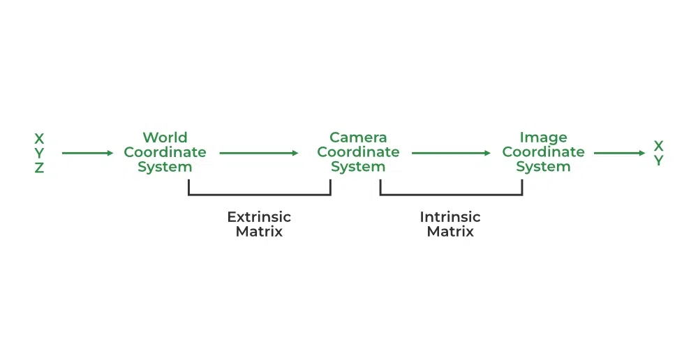
Object to Image Coordinate System
Usually, two types of distortion happen in an image. First radial distortion, causes straight lines to look slightly twisted or bent when a camera photographs them. Second, Tangential distortion, which causes the picture to be extended slightly longer or skewed and causes the objects to appear closer or farther away than they actually are, is most commonly caused by the lens not being parallel to the imaging plane.
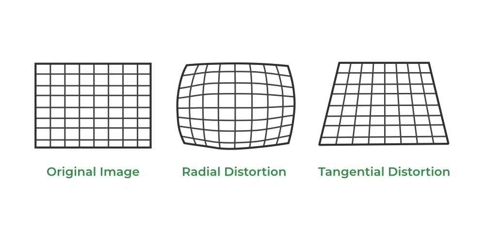
Distortion
The two major types of parameters required for calibration are as follows:
Extrinsic Parameters: It includes the orientation of the camera in the World Coordinate System by rotation and translation matrix.
The extrinsic matrix can be represented as : Matrix = [Rotation | Translation] i.e M=[ R | T ]
Intrinsic Parameters: It include the lens system parameters such as focal length, optical center, aperture, field-of-view, resolution, etc
The intrinsic matrix is represented by the focal length (fx,fy), optical center (cx, cy),
and the skew between axes(y) mostly as

The calibration procedure includes solving the given matrices using basic geometric equation calculations. The equations are chosen depending on the calibration objects. Opencv, to date supports three types of objects for calibration:
- Classical black-white chessboard
- Symmetrical circle pattern
- Asymmetrical circle pattern
Syntax of cv2.calibrateCamera()
Syntax:
cv2.calibrateCamera( objectPoints, imagePoints, imageSize, cameraMatrix, distCoeffs, rvecs, tvecs)
Parameters:
- objectPoints : a 3D point vector of vectors. Elements as many as number of pattern views are present in the outer vector.
- imagePoints : a vector of vectors of the 2D image points.
- imageSize : Size of image to initialise the camera matrix
- cameraMatrix : Intrinsic Camera Matrix. Mathematically, the transformation of 3D object points P(x,y,z) to image (x,y) is done by the transformative Camera Matrix (C) used for calibration.
- distCoeffs : Vector of lens’ radial and tangential distortion coefficients’
- rvecs : 3 x 1 rotaion vector. The axis of rotation is specified by the vector’s direction, and the angle of rotation is specified by the vector’s magnitude.
- tvecs : 3 x 1 translation vector
Returns:
- ret : the overall RMS re-projection error in floating number format.
Other estimations can also be returned as:
- Camera Matrix : The focal length and optical centre matrix as shown in intrinsic parameters
- Distortion Coefficients :
 which include radial (
 ) and tangential (
 ) distortion values
 - Rotation Vector : The image pixel rotation angles in radians converted to vector by Rodrigues method
- Translation Vector : The vector depicting shift in pixel values along x and y axis
Implementation:
Input: Asymmetrical circular grid image is used in the code below as input. No measurement of the circular unit size is necessary in circular grid. Fewer pictures are needed than other objects supported by opencv.
Input images link : https://github.com/PawanKrGunjan/Image-Processing/tree/main/calibrateCamera/Images
Step 1: The opencv and numpy libraries are imported and the termination criteria to stop the iteration (to be used further in code) is declared.
Step 2: A vector for real world coordinates of the circular grid is created. As measurement of actual circular unit is not needed, so vector is appended with random grid values. Also obj_points and img_points vectors are created to store 3D and 2D points of input image.
Step 3: The distorted image is then loaded and a grayscale version of image is created.
Step 4: Either the cv::findChessboardCorners or the cv::findCirclesGrid function can be used, depending on the type of input (chessboard or circular grid) to get the position of pattern by passing the current image and the board size. Boolean value is returned to indicate if the pattern was included in the input. If its true, 3D object points are updated.
Step 5: When multiple images are used as input, similar equations might get created during calibration which might not give optimal corner detection. Hence cv.cornerSubPix() function analyses images and corners to give better results. Since the algorithm is iterative, we must define the termination criteria (such as the number of iterations and/or accuracy). In circular grids, this function is not always necessary.
Step 6: The 2D image points are also updated from the optimal corner values. Then, using a call to drawChessboardCorners() that inputs our image, corner measurements, and points that were detected are drawn and saved as output image.
Step 7: The calibrateCamera() function is called with the required parameters and output is displayed.
Step 8: Finally, the error, the camera matrix, distortion coefficients, rotation matrix and translation matrix is printed.
Python3
import numpy as np
import cv2 as cv
import glob
criteria = (cv.TERM_CRITERIA_EPS + cv.TERM_CRITERIA_MAX_ITER, 30, 0.001)
obj3d = np.zeros((44, 3), np.float32)
a = [0, 36, 72, 108, 144, 180, 216, 252, 288, 324, 360]
b = [0, 72, 144, 216, 36, 108, 180, 252]
for i in range(0, 44):
obj3d[i] = (a[i // 4], (b[i % 8]), 0)
obj_points = []
img_points = []
images = glob.glob('./Images/*.png')
for f in images:
img = cv.imread(f)
gray = cv.cvtColor(img, cv.COLOR_BGR2GRAY)
ret, corners = cv.findCirclesGrid(
gray, (4, 11), None, flags=cv.CALIB_CB_ASYMMETRIC_GRID)
if ret == True:
obj_points.append(obj3d)
corners2 = cv.cornerSubPix(gray, corners, (11, 11), (-1, -1), criteria)
img_points.append(corners2)
cv.drawChessboardCorners(img, (4, 11), corners2, ret)
cv.imwrite('output.jpg', img)
cv.imshow('img', img)
cv.waitKey(0)
cv.destroyAllWindows()
ret, camera_mat, distortion, rotation_vecs, translation_vecs = cv.calibrateCamera(
obj_points, img_points, gray.shape[::-1], None, None)
print("Error in projection : \n", ret)
print("\nCamera matrix : \n", camera_mat)
print("\nDistortion coefficients : \n", distortion)
print("\nRotation vector : \n", rotation_vecs)
print("\nTranslation vector : \n", translation_vecs)
|
Output:
Error in projection :
 0.28397138993192417

Camera matrix :
 [[ 2.98018946e+03  0.00000000e+00 -2.07790644e+02]
 [ 0.00000000e+00  2.98680309e+03  5.80328416e+02]
 [ 0.00000000e+00  0.00000000e+00  1.00000000e+00]]

Distortion coefficients :
 [[-1.38990879e+00  1.28121501e+01 -1.76642504e-02  4.92392900e-02
  -6.65051660e+01]]

Rotation vector :
 (array([[1.98945525],
       [2.57035288],
       [0.00544978]]), array([[-2.141599  ],
       [-1.96709247],
       [ 0.1071076 ]]), array([[-2.30654667],
       [-1.91925376],
       [-0.09466172]]), array([[-2.14337584],
       [-1.80887689],
       [-0.09635144]]), array([[-1.89996746],
       [-1.89926953],
       [ 0.33507546]]))

Translation vector :
 (array([[ 465.62345471],
       [-601.35082796],
       [3539.69468578]]), array([[ 549.35638975],
       [-550.85288875],
       [3547.04309867]]), array([[ 286.79704145],
       [-575.92278998],
       [3538.10081969]]), array([[ 379.75106914],
       [-604.7774144 ],
       [3469.45627266]]), array([[ 505.52036258],
       [-533.92939056],
       [3465.54276018]]))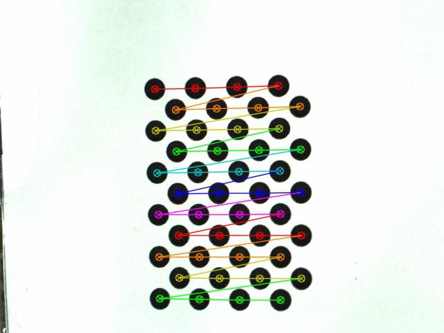
Output Image
Output Explanation:
The ret variable is used to print the Error in projection i.e. the overall RMS re-projection error.
The Camera Matrix displays the intrinsic parameters of the camera which is focal length and optical center values.
The Distortion Coefficients Matrix has five values in the form of where indicates radial distortion and indicates tangential distortion values.
The Rotation Vector depicts the rotation axis of images and the length of the vector encodes the rotation’s angle in radians.
The Translation Vector depicts the values of translation of images i.e. the required shift in pixels values
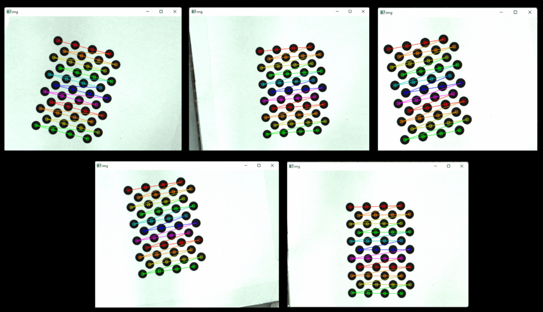
Output Images
Share your thoughts in the comments
Please Login to comment...