In the complex realm of electronic circuits, the concept of Miller capacitance stands as a pivotal detail, weaving its influence through amplifiers and diverse sign-processing devices. Named after the prominent engineer John Milton Miller, this capacitance phenomenon is at the center of expertise in the intricacies of excessive-frequency circuit behavior.
At its essence, Miller capacitance manifests itself through the Miller Effect—a phenomenon where the plain capacitance among nodes in a circuit is augmented inside the presence of voltage amplification. As a result, the consequences of Miller capacitance reverberate throughout the performance landscape of electronic systems, influencing impedance characteristics, frequency response, and balance.
This article embarks on a comprehensive exploration of Miller’s capacitance, aiming to demystify its intricate sides for amateur enthusiasts and pro engineers. From dissecting the Miller Effect to unraveling its effect on numerous digital components, together with Insulated Gate Bipolar Transistors (IGBTs), this adventure delves into the theoretical underpinnings and sensible programs.
Throughout the discourse, visual aids, together with diagrams and solved examples, will remove darkness from the nuanced nature of Miller’s capacitance. Moreover, the exploration extends to its function in radio frequency (RF) and microwave circuits, imparting insights into its adaptability throughout various frequency spectrums.
What is the Miller Effect?
The Miller Effect describes the plain growth in capacitance between two nodes in a circuit while voltage amplification is present. This phenomenon is specially applicable in electronic gadgets with amplifying components, which includes transistors and operational amplifiers.
Effect of Miller Capacitance
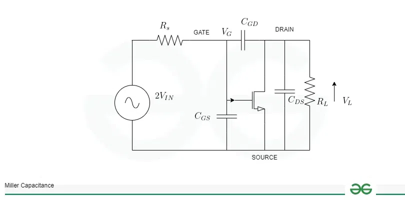
Miller capacitance impacts the enter and output impedance of a circuit, influencing its ordinary overall performance. A targeted explanation, accompanied through diagrams, will illustrate how this capacitance alters the circuit traits.
Miller effect capacitance
Miller Effect in IGBT
The Miller Effect, a phenomenon characterized by the plain increase in capacitance because of voltage amplification, plays a important position inside the conduct of Insulated Gate Bipolar Transistors (IGBTs). IGBTs are semiconductor gadgets widely used for high-energy applications, including motor drives, electricity inverters, and amplifiers.
In an IGBT, the Miller Effect is specially considerable on the input and output terminals. When a voltage is carried out to the gate terminal, it controls the conductivity between the collector and emitter terminals. The amplification of this voltage via the Miller Effect can cause an increased effective capacitance between the collector and emitter.
How it Works ?
- Gate-Collector Capacitance: The gate-collector capacitance (CGC) is a vital parameter in IGBTs. The Miller Effect arises as the voltage across this capacitance is amplified because of the voltage benefit of the transistor.
- Increased Input Capacitance: The obvious increase within the gate-collector capacitance efficiently increases the input capacitance of the IGBT, impacting the input impedance of the tool. This phenomenon is illustrated within the diagram, showcasing the additional capacitance (CMiller) due to the Miller Effect.
- Impact on Switching Speed: The Miller Effect can affect the switching velocity of IGBTs. As the powerful input capacitance increases, the time required to rate and discharge this capacitance impacts the switching traits, probably leading to delays and affecting the general performance of the device.

IGBT(Insulated Gate Bipolar Transistors)
Miller Capacitance Equation
The Miller capacitance (CMiller) is a crucial parameter in electronic circuits, in particular in amplifiers. It quantifies the plain increase in capacitance between nodes due to the Miller Effect, that’s typical in devices with voltage gain. The equation for Miller capacitance is derived from the relationship between the actual capacitance (C) and the voltage gain (AV):
CMiller =C× (1 + Av)
Where,
• CMiller is the Miller capacitance.
• C is the actual capacitance among two nodes (e.G., between the input and output terminals of a transistor).
• AV is the voltage gain of the amplifier or the digital tool.
The Miller capacitance equation reveals that the effective capacitance experienced between the nodes is immediately proportional to the actual capacitance and is magnified with the aid of the voltage advantage. This courting emphasizes the impact of amplification on the circuit’s obvious capacitance.
Solved Example on Miller Capacitance
Q. Consider a not unusual-emitter amplifier with a transistor having a voltage gain(Av) of 40. The input capacitance among the base and collector terminals is CBC =10pF. Determine the effective input capacitance (CMiller) whilst considering the Miller Effect.
Solution
AV = Voltage gain
Formula to calculate Miller capacitance (CMiller)
(CMiller) = CBC ✖ (1 + AV)
Given that AV = 40 and CBC = 10pF, here we can substitute this value in the formula,
CMiller = 10pF ✖ (1 + 40)
CMiller=10pF ✖ 41
CMiller =410pF
Therefore, the effective input capacitance (CMiller) in the presence of the Miller Effect is 410 pF.
Effects on Frequency Response
The Miller Effect, characterized by the plain growth in capacitance due to voltage amplification, exerts a profound influence at the frequency reaction of digital circuits. Understanding how Miller capacitance impacts the frequency reaction is important for designing circuits that operate optimally throughout a number of frequencies.
• High-Frequency Roll-Off: The Miller Effect effectively will increase the capacitance visible at positive nodes inside the circuit, causing a excessive-frequency roll-off. As the frequency increases, the amplified capacitance will become greater giant, affecting the impedance at excessive frequencies. This phenomenon effects in a discount of the higher cutoff frequency of the circuit.
• Bandwidth Limitations: Miller capacitance introduces obstacles at the bandwidth of the circuit. The extended effective capacitance affects the time constants within the circuit, main to slower response times at higher frequencies. This bandwidth hassle is a essential attention in programs in which a extensive frequency range is important.
• Phase Shift: The Miller Effect also can set off phase shifts inside the frequency reaction. As the capacitance will increase with frequency, it impacts the phase dating among the input and output alerts. This section shift can be specially complicated in feedback structures and might cause instability if no longer cautiously managed.
• Compromised High-Frequency Performance: In high-frequency programs, Miller capacitance can compromise the general overall performance of the circuit. Amplifiers, as an instance, can also enjoy decreased benefit at high frequencies, impacting their ability to as it should be increase alerts across the complete frequency spectrum.
• Mitigation Strategies: Engineers hire diverse strategies to mitigate the damaging outcomes of Miller capacitance on frequency response. These can also include the usage of repayment techniques, using bandwidth-enhancing circuit topologies, and thoroughly choosing aspect values to balance the trade-offs among gain and bandwidth.
Miller Capacitance in RF and Microwave Circuits
Miller Capacitance in RF(Radio Frequency) Circuits
In the short-paced global of RF engineering, Miller capacitance significantly impacts circuit performance. Operating in the GHz variety, RF circuits require unique impedance matching, that’s disrupted by way of the Miller Effect. RF amplifiers, filters, and resonators are all affected, traumatic careful consideration throughout design. Engineers deploy layout optimization, transistor configurations, and reimbursement techniques to mitigate the effect and make certain stable and green RF overall performance.
Miller Capacitance in Microwave Circuits
Microwave circuits, working at several hundred GHz, face heightened demanding situations due to the Miller Effect. Miller capacitance substantially amplifies at those frequencies, impacting microwave filters, resonators, and transistors. Microwave amplifiers are mainly sensitive, requiring reimbursement strategies. The role of Miller capacitance in transmission lines, which include microstrip lines, emphasizes its have an effect on on green sign propagation in excessive-frequency microwave programs. Engineers have to appoint superior layout strategies for a success microwave circuitry in modern wi-fi communication structures.
Impact on Amplifier Stability
The impact of Miller capacitance on amplifier stability is a important consideration in electronic circuit design. Stability is paramount to make sure reliable and predictable circuit behavior, mainly in programs which includes audio amplifiers and radio frequency systems. Let’s explore how Miller capacitance affects amplifier stability, followed with the aid of a illustrative diagram.
- Effect on Feedback Networks: Amplifiers regularly contain remarks networks to alter gain and enhance balance. Miller capacitance introduces an apparent boom in capacitance inside these networks, influencing the general remarks loop.
- Phase Shift and Instability: The amplification of capacitance because of the Miller Effect introduces segment shifts inside the feedback loop. Excessive section shift can lead to instability, oscillations, and unpredictable behavior inside the amplifier.
- Compensating for Stability: To counteract the destabilizing effects of Miller capacitance, compensation strategies are hired. Common techniques encompass neutralization circuits and strategic placement of compensating capacitances to restore balance without compromising other performance parameters.

Amplifier Stability
- Illustrative Diagram: A diagram depicting an amplifier circuit with feedback loops and highlighting the nodes laid low with Miller capacitance visually illustrates the impact on balance. The diagram showcases how the plain increase in capacitance affects the remarks mechanism, contributing to section shifts and capability instability.
Advantages and Disadvantages of Miller Capacitance
Given Below are Advantages and Disadvantages of Miller Capacitance
Advantages
- Voltage Amplification: Miller capacitance contributes to voltage amplification in amplifiers. By effectively increasing capacitance, it permits for better voltage gains in positive configurations, enhancing the overall overall performance of amplifying gadgets.
- Frequency Compensation: In a few instances, Miller capacitance can offer a diploma of frequency repayment, taking into consideration tailor-made responses in filter out networks and different frequency-structured circuits.
- Simplified Design: In positive amplifier configurations, Miller capacitance can simplify design considerations by means of facilitating coupling among stages, lowering the want for additional additives.
Disadvantages
- Frequency Limitations: The amplification of capacitance through the Miller Effect introduces barriers on the excessive-frequency reaction of circuits. This can result in reduced bandwidth and performance at better frequencies.
- Impedance Changes: Miller capacitance alters the impedance traits of circuits, affecting enter and output impedance. This can complicate impedance matching and effect the general balance of the circuit.
- Phase Shift and Instability: The increase in capacitance can introduce phase shifts in feedback loops, leading to instability in amplifiers. Uncontrolled instability may additionally result in oscillations and unpredictable behavior.
Applications of Miller Capacitance
- Oscillators: In the design of oscillators, where preserving balance and controlling frequency are crucial, Miller capacitance can play a position in shaping the frequency response and comments traits.
- Mixers and Modulators: Miller capacitance is applicable in mixers and modulators, contributing to the signal processing and frequency conversion functionalities in communication structures.
- Voltage-Controlled Oscillators (VCOs): Miller capacitance is a factor in VCOs, which might be critical additives in frequency synthesizers, assisting generate variable-frequency indicators.
- Analog Filters: In analog filter out circuits, Miller capacitance influences the characteristics of low-skip, high-pass, and band-skip filters, impacting their frequency response.
- Photodetectors: In optoelectronic applications, along with photodetectors, Miller capacitance can influence the response time and bandwidth of the devices.
- Mixer Circuits in RF Receivers: Miller capacitance is a consideration in mixer circuits inside RF receivers, influencing the signal processing and down-conversion tiers.
- Phase-Locked Loops (PLLs): Miller capacitance impacts the stableness and overall performance of PLLs, which might be generally used in frequency synthesis and synchronization packages.
- Switched-Capacitor Circuits: In switched-capacitor circuits, frequently hired in analog signal processing, Miller capacitance impacts the powerful capacitance at some point of switching operations.
- Voltage Regulators: In voltage regulators, specifically those utilized in power control circuits, Miller capacitance can impact the stability and transient response of the regulator.
- Delay Lines: In certain programs like phased-array antennas, Miller capacitance can be a consideration in delay lines, influencing signal propagation times.
Conclusion
In precis, Miller capacitance, a outcome of the Miller Effect, is a double-edged sword in electronic circuit design. While it complements voltage amplification and reveals applications in numerous circuits like amplifiers and filters, its drawbacks include frequency limitations and capacity instability. Engineers should strike a delicate balance, leveraging its advantages whilst using reimbursement techniques to control its destructive results. The nuanced knowledge of Miller capacitance is vital for crafting reliable and efficient digital systems at some stage in numerous programs within the ever-evolving technological panorama.
FAQs on Miller Capacitance
1. What is Miller Capacitance, and the way does it fluctuate from normal capacitance?
Miller Capacitance is the apparent boom in capacitance between two nodes in a circuit due to the Miller Effect, wherein voltage amplification is present. It differs from regular capacitance by means of being amplified via a aspect of (1 voltage gain).
2. How does Miller Capacitance have an effect on amplifier balance, and what reimbursement strategies are normally used?
Miller Capacitance can introduce segment shifts and instability in amplifiers. Compensation strategies consist of neutralization circuits and strategically positioned compensating capacitances to restore balance.
3. In which applications is Miller Capacitance in particular relevant?
Miller Capacitance is important in packages like amplifiers, filters, oscillators, RF, and microwave circuits. It plays a massive role in shaping frequency responses and influencing stability in these circuits.
4. How does Miller Capacitance impact the frequency response of electronic circuits?
Miller Capacitance introduces limitations on high-frequency response, leading to decreased bandwidth. It can affect the general frequency characteristics of circuits, particularly in RF and microwave programs.
5. What are the blessings and disadvantages of Miller Capacitance?
Advantages include more advantageous voltage amplification, simplified designs, and potential frequency compensation. Disadvantages encompass frequency obstacles, impedance changes, and the chance of instability in amplifiers.
Share your thoughts in the comments
Please Login to comment...