Sample and Hold Circuit
Last Updated :
26 Feb, 2024
Sample and Hold Circuit is a circuit that used in signal processing and data procurement system. The main function of this system is to transmit the signal and sample the input value and hold or freeze this processed value for some time. This circuit permits the circuit to catch and manage the instantaneous data or value of the signal and this is useful in many fields. It consists of switches, capacitors, operational amplifier (op-amp) and control signal (sample-and-sold control).
What is Sample and Hold Circuit?
The Sample and Hold circuit is a circuit used in electronics to generate or produce the samples of voltage given to input, and after processing it, holds this voltage for a specific or unique time. The time in which the circuit samples and holds voltage and produces the incoming signal is known as sampling time. Same as the time period of this circuit which holds the processed value is known as holding time. Basically it creates the sample of voltages as the input term and after that holds these samples for a definite period of time. We can say that the capacitor is the main working operator of the sample and holds the circuit as it charges to its peak value and then the switch is opened.

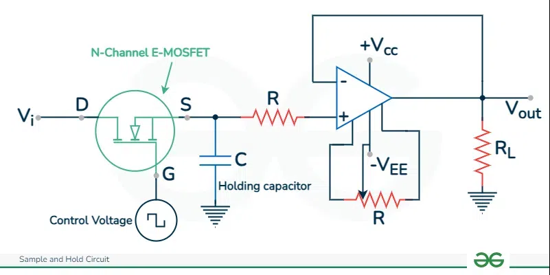
Circuit Diagram of Sample and Hold Circuit
Working of Sample and Hold Circuit
The main components in a sample and hold circuit is an N-Channel E-MOSFET, a capacitor to store, hold and release the electric charge and a high operational amplifier. The N-channel E-MOSFET will be used as changing component. The incoming voltage is entering the terminal and control voltage will be entering through gate terminal, After that, when the positive beat of voltage is applied, the E-MOSFET will be changed to ON means open. After that, it acts as a shut or close switch. In actuality, when the voltage is zero then the MOSFET will be changed to switch OFF state and acts about as the open switch.
At that point, when the MOSFET acts about as a close switch, after that point, the simple signal is applied to it through the terminal will be fed to the capacitor. The capacitor will then, at that point, charge to its maximum value. Then, when the MOSFET switch is ON, after that point, the capacitor quits charging. Because of the great amplifier attached to the finish of the circuit, the capacitor will face great impedance because of this it can’t get released or discharge. The capacitor holds the voltage for some specific period of time. This time period is also known as holding time period and the time in which the samples of voltage produce is called sampling time period
The processed voltage by amplifier during the holding period. Hence, holding period holds significance for OP-AMPs.
Circuit Diagram
Input and Output Waveforms
The waveforms represent in the diagram clearly prompts the picture. It is conclusion from the waveform of the sample and hold circuit, on processing during the Open or ON duration what will be the voltage at the output and during the Close or OFF duration what will be the voltage at the output of OP-AMPs.
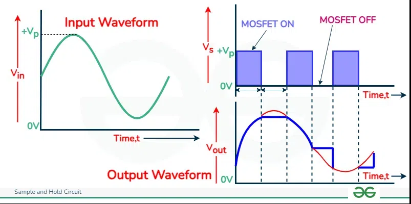
Input and Output Waveform
Connection in Sample and Hold Circuit
To sample the input signal, the switch connects the capacitor to the output of a buffer amplifier. The connection tells about the control voltage and input voltage and how both of them applied on the OP-AMPs. In this circuit the capacitor is made up of Polyethylene and Teflon. In above diagram, the frequency of analog input signal and control signal is noted and it is very important to balance the power of this circuit to noted the frequency. The control voltage’s frequency should be higher than input voltage’s frequency that’s why the simple signal can be sampled two times in a whole cycle. During the sample phase, the input signal is connected to the capacitor through a switch. The capacitor charges or discharges to the input signal voltage. And in the hold phase, the switch is opened, disconnecting the input signal from the capacitor.

Connection in Sample and Hold Circuit
Functional Diagram
The main function of a sample-and-hold (S/H) circuit is to take samples of its input signal and hold these samples in its output for some period of time. Typically, the samples are taken at uniform time intervals; thus, the sampling rate (or clock rate) of the circuit can be determined.

Functional Diagram in Sample and Hold Circuit
Types of Sample and Hold Circuit
There are many types of S and H circuit:
- Switched Capacitor Sample and Hold Circuit: It is a type of sample and hold circuit and also a type of simple circuit commonly used in simple – to – advance converters or analog – to – digital converters (ADCs) and in other programs where the correct sampling and holding of an simple signal is necessary.
- Track and Hold (T&H) Circuit: It is a type of sample and hold circuit that is used to sample an approaching or incoming of simple or analog signs and hold the level of voltage for a unique period of time.
- Holding Amplifier Sample and Hold Circuit: It is a type of sample and hold circuit that is used in system with principle of S and H circuit and is is responsible for balancing the level of voltage during samples the signals and holding the signals. It protects circuit until one sampling and holding complete.
- MOSFET Switch Sample and Hold Circuit: It is a type of sample and hold circuit and it connects the input voltage to the capacitor, allowing or permitting it to charge and store the sampled voltage.
- Voltage-Controlled Sample and Hold Circuit: It is also a type of sample and hold circuit and also a simple electronic system that is used to sample an incoming voltage and hold that process voltage until the next sampling occurs. It finds in various fields like (ADCs), audio affects and other applications where it is used in sampling and holding the signals.
- Pulse Sample and Hold Circuit: It is a type of sample and hold circuit that generally used in applications where exact timing is essential or crucial, like in information procurement and data acquisition systems and analog – to – digital converters (ADCs).
Performance Parameters of Sample and Hold Circuit
- Aperture Time (TAP): It can be described as the expected or required time used by the capacitor to switch its position from sampling to holding. It is known as aperture time or opening time.
- Acquisition Time (TAC): It can be described as expected or required time used by the capacitor to get the charge of the incoming voltage applied to the sample and hold circuit. It is known as acquisition time or securing time.
- Voltage Droop: The capacitor in this circuit have a drop down voltage because of spillage of charge by a capacitor. But in realty, we want a capacitor with zero linkage but it is impossible.
- Hold Mode Settling Time: After the commands of the hold applied, the simple or analog incoming voltage within a specific error and takes some time for completion. This required time is known as Hold Mode settling time.
.png)
Performance Parameters
Applications of Sample and Hold Circuit
- The main application of sample and hold circuit is in simple to advance or analog to digital converters (ADCs) and it is used to catch and keep the simple incoming pr input voltage until it is change into advance value.
- These circuits are often used in communication programs or applications and in processing of signs to remake the simple or analog signals from the different samples.
- These circuits can be used regulation of voltage applications to immediately store a reference voltage and then which is used to direct and settle the result voltage of a power.
- These circuits are often used in medical screening or imaging. With the help of sample and hold circuit we use to capture and hold the adequacy of signs from sensors like X-ray machines, ultrasound machines and city scan.
- These circuits are also used in many tools and applications like (ADCs), communication tools, signal processing applications.
Advantages of Sample and Hold Circuit
- It increases the stability of signals by sampling and holding the signals and also prevents from any changes at this time.
- It also helps in conversion of simple signals into advance signals by the use of this circuit in analog to digital converters (ADCs).
- It also helps in processing of signals in communication applications by samples the signals and hold for specific time-frame. In other words, this circuit catch the signals and processed it at specific interval or period time.
- It also used in changing the circuits to remove unwanted or undesirable things that may be occur during changing process. It also reduces the noise in simple signals.
- It also plays a important or main role in information procurement or data acquisition application where exact and limiting sampling of simple signals is done and it is essential for processing done.
Disadvantages of Sample and Hold Circuit
- Due to limited, exact or specific period of time interval the chances of errors are increases during processing of signals.
- The applications with high frequency level, the quickly moving signal can not be sampled easily due to this the sample and hold circuit can not processed the signals accurately.
- These circuits also causes temperature variations because this is also a electronic circuit. When the temperature changes it can affects or influence the properties of components which leading mistakes during process.
- The applications with very heavy physical size and intricacy or complexity is also bad and disadvantage for this circuit.
Conclusion
A sample and hold circuit is a important circuit in various electronic systems, mainly in ADCs and in data or information procurement systems. The main purpose of a this sample and hold circuit is to to transmit the signal and sample the input value and hold or freeze this processed value for some time. It is used in electronics to generates or produce the samples of voltage given to input, and after processed it, holds these voltage for the specific or unique time. The main components in a sample and hold circuit is an N-Channel E-MOSFET, switch, a capacitor to store, hold and release the electric charge and a high operational amplifier. The switch samples the incoming signal which enters from the drain terminal of E-MOSFET and charges the capacitor to hold the voltage remains stop while the switch is ON. This circuit permits the circuit to catch and manage the instantaneous data or value of the signal and this is useful in many fields.
FAQs on Sample and Hold Circuit
What is the importance of a sample and hold circuit in ADCs?
In Analog to Digital Converters, these circuits play a crucial role in accurately sampling the simple incoming or input signal and holding it during the conversion process of simple signal to advance signal. This circuit is very useful and important in various fields.
What is the purpose of a sample and hold circuit?
The main purpose of a this sample and hold circuit is to to transmit the signal and sample the input value and hold or freeze this processed value for some time. It is used in electronics to generates or produce the samples of voltage given to input, and after processed it, holds these voltage for the specific or unique time.
How does a sample and hold circuit work?
The main components in a sample and hold circuit is an N-Channel E-MOSFET, switch, a capacitor to store, hold and release the electric charge and a high operational amplifier. The switch samples the incoming signal which enters from the drain terminal of E-MOSFET and charges the capacitor to hold the voltage remains stop while the switch is ON.
How many performance parameter in sample and hold circuit?
There are four types of performance parameter in sample and hold circuit are given below:
- Acquisition Time (TAC)
- Aperture Time (TAP)
- Voltage Droop
- Hold Mode Settling Time
Share your thoughts in the comments
Please Login to comment...