LC Circuit is a special type of electric circuit that is made up of an Inductor and a Capacitor. The inductor is represented by using the symbol L whereas the capacitor is represented using the symbol C. Hence, the name LC Circuit. LC Circuit acts as a major electric component in various devices such as oscillators, tuners, and filters. Thus LC circuit finds a number of applications in daily life. In this article, we shall discuss the LC circuit in detail.
What is LC Circuit?
LC Circuit is also known as a “tank circuit” or “inductor-capacitor circuit”. LC Circuit is a simple electrical circuit that consists of two main components: an inductor and a capacitor. These components can further be added together in series or parallel configurations based on the required task at hand. An LC circuit is used to store electrical energy in the circuit with the help of magnetic resonance.
The energy or current in an LC circuit oscillates between the inductor and capacitor just like a pendulum swings back and forth. An LC circuit is used to store electrical energy in the circuit with the help of magnetic resonance. Resonance in an LC circuit occurs when the magnitude of inductive reactance and capacitive reactance in the LC circuit becomes equal. The frequency at which this occurs is known as resonant frequency.
The energy stored in an LC circuit gets exhausted if the source of energy is disconnected due to the internal resistance offered by the circuit as the current moves back and forth between the inductor and capacitor in an LC circuit.
Types of LC Circuit
The arrangement of this inductor and capacitor leads to the development of two types of LC circuits which are
- Series LC Circuit
- Parallel LC Circuit
Let’s discuss these types in detail.
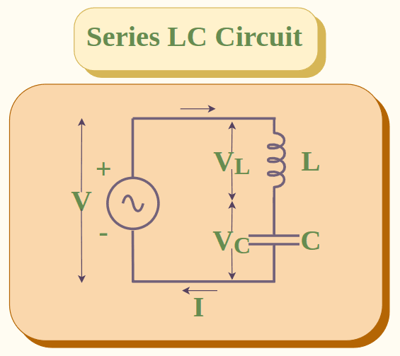
Series LC Circuit
In a series LC circuit, capacitor C and inductance L are connected in series with each other. A series LC circuit is shown below:
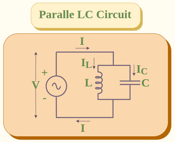
Parallel LC Circuit
In a series LC circuit, capacitor C and inductance L are connected in parallel with each other. A parallel LC circuit is shown below:
What is Inductor?
An inductor is an electrical component that is used to store energy in the form of magnetic energy. It is widely used in many electronics and electrical appliances. Inductor can also be called as choke coil. The strength of inductor is measured in terms of inductance and depends on various factors such as shape of inductor, number of turns in inductor, material of inductor and space between the turns in the inductor coil. Inductance of an inductor is measured in Henry (H).
Inductance in LC Circuit
Inductance in an LC circuit is the measure of the magnitude of the inductor connected in the LC circuit. SI unit of inductance is Henry (H) and the inductance of LC circuit is represented by L. It is calculated as:
L = μ0 N2 A/l
Where,
- L is the inductance in henrys (H)
- μ₀ is the permeability of free space, [μ₀ = 4π × 10-7 H/m]
- N is the number of turns of wire in the coil
- A is the cross-sectional area of the coil in square meters (m²)
- l is the length of the coil in meters (m)
What is Capacitor?
An inductor is an electrical component that is used to store energy in the form of electrical energy between the plates of the capacitor. It is widely used in many electronics and electrical appliances for tuning purposes and change in frequency. The strength of capacitor is measured in terms of capacitance and depends on various factors such as material between the plates of conductor, area of the plates, distance between the plates, etc. Capacitance of a capacitor is measured in Farad (F).
Capacitance in LC Circuit
Capacitance in an LC circuit is the measure of the magnitude of the capacitor connected in the LC circuit. SI unit of capacitance is Farad (F) and the capacitance of LC circuit is represented by C. It is calculated as:
C = q/V
where q and V represent charge and potential difference across the plates of the capacitor
Resonance in LC Circuit
Resonance in an LC circuit occurs when the magnitude of inductive reactance and capacitive reactance is equal and they have a phase difference of 180 degrees i.e. they are equal and opposite to each other. It means that the resonance is a condition when the inductance and capacitance cancel out each other. Now we shall discuss resonance in series and parallel LC circuit in detail.
Resonance in Series LC Circuit
Consider a series LC circuit with VL and VC as the potential difference across inductor and capacitor respectively and I is the current through the circuit and V is the net potential difference across the circuit.
We know that in a series circuit the current across the circuit is the same. Thus current across inductor IL and current across capacitor IC are the same.
I = IL = IC
The total potential difference across the circuit is the sum of the potential differences across inductor and capacitor.
V = VL + VC
The condition for resonance is that magnitude of inductive reactance XL and magnitude of capacitive XC are equal. Thus, resonance occurs when:
XL = XC
We know that,
XL = ωL = 2πfL
XC = 1/(ωC) = 1/(2πfC)
where,
- ω is the angular frequency of the circuit
- f is the frequency of the circuit
Resonance Frequency In LC Series Circuit
Resonance occurs when:
XL = XC
ωL = 1/( ωC)
ω2 = 1/LC
ω = 1/√LC
As ω = 2πf
f = ω/2π
f = 1/2π√LC
Thus, at resonance the frequency of circuit is 1/2π√LC and is denoted by f0.
Impedance in Series LC Circuit
Impedance of an LC circuit is the net resistance of the LC circuit. It is the effective resistance offered by the inductor as well as capacitor in the LC circuit. Impedance is represented by symbol Z.
We know that when two resistors are connected in series then effective resistance is the sum of resistances of the individual resistors. Consider a series LC circuit with RL and RC as the resistance of the inductor and capacitor respectively. Thus impedance or net resistance of series LC circuit is given by:
Z = RL + RC
Z = jωL + 1/jωC
where j2 = -1
Z = jωL – j2/jωC
Z = jωL – j/ωC

At resonance ω = ωo= 1/√LC. Thus impedance of series LC circuit becomes zero as follows:

Resonance in Parallel LC Circuit
Consider a parallel LC circuit with IL and IC as the currents across inductor and capacitor respectively and I is the current through the circuit and V is the net potential difference across the circuit.
We know that in a parallel circuit the potential difference across the circuit is the same. Thus potential difference across inductor VL and potential difference across capacitor VC are the same.
V = VL = VC
The total current across the circuit is the sum of the currents across inductor and capacitor.
I = IL + IC
The condition for resonance is that magnitude of inductive XL and magnitude of capacitive XC are equal. Thus, resonance occurs when:
XL = XC
We know that,
XL = ωL = 2πfL
XC = 1/( ωC) = 1/(2πfC)
where ω is the angular frequency of the circuit and f is the frequency of the circuit.
Resonance Frequency In Parallel LC Circuit
Resonance occurs when:
XL = XC
ωL = 1/( ωC)
ω2 = 1/LC
ω = 1/√LC
As ω = 2πf
f = ω/2π
f = 1/2π√LC
Thus, at resonance the frequency of circuit is 1/2π√LC and is denoted by f0. Some important points about resonant frequency in LC circuit are:
- If f < f0 then XC >> XL. Thus the circuit is capacitive in nature.
- If f < f0 then XC << XL. Thus the circuit is inductive in nature.
Impedance in Parallel LC Circuit
We know that when two resistors are connected in parallel then effective resistance is the sum of reciprocal of the resistances of the individual resistors. Consider a parallel LC circuit with RL and RC as the resistance of the inductor and capacitor respectively. Thus impedance or net resistance of parallel LC circuit is given by:
1/Z = 1/RL + 1/RC
1/Z = (RL+RC)/RLCL
Z = RLRC/(RL+RC)

At resonance ω = ωo = 1/√LC. Thus impedance of parallel LC circuit becomes infinity as follows:

Voltage and Current in LC Circuit
Let I(t) be the current in LC circuit at any instant. Thus potential difference across inductor becomes:
VL = LdI(t)/dt
The potential difference across capacitor becomes:
VC = q/C
According to Kirchoff’s law, the sum of potential differences across different components in a closed circuit is zero and as LC circuit is closed circuit:
VL + VC = 0

Dividing LHS and RHS by L and differentiating both sides w.r.t ‘t’, we get:
![\frac{d^2I(t)}{dt^2} + \frac{d}{dt}(\frac{q}{LC}) = 0\\ \frac{d^2I(t)}{dt^2} + \frac{1}{LC}[\frac{d}{dt}({It})] = 0\\ \frac{d^2I(t)}{dt^2} = \frac{-1}{LC}[I(t)]](https://www.geeksforgeeks.org/wp-content/ql-cache/quicklatex.com-cdfbe9b17b17f1c0e559c03e17fa98d8_l3.png "Rendered by QuickLaTeX.com")
As an LC circuit follows SHM and we know that current in SHM is given by:

Differentiating both sides w.r.t ‘t’, we get:

The potential difference across an LC circuit is given by the equation:

Energy Stored in LC Circuit
In an LC circuit, energy is stored in two forms: magnetic energy in the inductor’s magnetic field and electric energy in the capacitor’s electric field. This energy oscillates back and forth between the electric and magnetic fields as the current and voltage oscillate. At any given moment, the total energy in the circuit is the sum of the energy stored in the inductor and the energy stored in the capacitor, and it is always constant.
The energy stored in an LC circuit, which consists of a capacitor (C) and an inductor (L), is given by the formula:
E= q2/2C + 1/2 LI2
Where,
- E is the Total energy stored in the circuit in joules (J)
- q2/2C is the energy stored in the capacitor
- 1/2 LI2 is the energy stored in the inductor
- q is the charge on the surface of capacitor
- C is the capacitance of the capacitor
- L is the inductance of the inductor in henries (H)
- I is the current flowing through the circuit in amperes (A)
Note: Total Energy in any LC Oscillation Circuit remains contstant.
Quality Factor (Q) in LC Circuit
Quality factor or Q factor of an LC circuit is a measure of the goodness of the LC circuit an determines how efficiently the energy is transferred in a given LC circuit. It is generally desirable to have a high Q factor as it indicates less energy loss and high efficiency. Mathematically, we can define quality factor as the ratio of power dissipated across inductor to the power dissipated across resistance in an LC circuit.

where Q, I, X and R represent Quality Factor, current, inductance and resistance of the LC circuit.
Let us calculate Quality (Q) factor for series and parallel LC circuit.
Q-Factor in Series LC Circuit
We know that Q = XL/R.
As XL = ω0L
Q = ωoL/R
In a series LC circuit, at resonance:

Q-Factor in Parallel LC Circuit
The Q-Factor a parallel LC circuit is the inverse of the Q-factor of a series LC circuit. Thus Q-factor of a parallel LC circuit is given by:

Solved Problems on LC Circuit
Problem 1. Calculate the Q Factor in a series LC circuit with R = 3.1Ω, L = 7.1H and C= 5F.
Solution:
Given R = 3.1Ω, L = 7.1H and C= 5F
Q-Factor in Series LC circuit is calculated as:

Thus, Q = 0.38
Problem 2. Calculate the Q Factor in a parallel LC circuit with R = 13Ω, L = 6H and C= 3.7F.
Solution:
Given R = 13Ω, L = 6H and C= 3.7F
Q-Factor in parallel LC circuit is calculated as:

⇒ Q = 13√(0.62)
⇒ Q = 13 × 0.785
⇒ Q = 10.2
Problem 3. Calculate resonant frequency in an LC circuit with inductance = 41 H and capacitance = 2.7 F.
Solution:
Given L = 41H, C = 2.7F
In an LC Circuit resonant frequency is calculated as:

Thus, ω= 0.095
Problem 4. Calculate the inductance of a series LC circuit with resonant frequency of 3.7Hz and capacitance of 4F.
Solution:
Given ω = 3.7 Hz, C = 4 F
Thus, using the formula we get

Thus, L = 0.018H
Problem 5. Calculate the capacitance of parallel LC circuit with inductance = 6.6H and resonant frequency = 7.3 Hz.
Solution:
Given ω = 7.3 Hz, L = 6.6H
Thus, using the formula we get

Thus, C = 0.028 F
Practice Problems on LC Circuit
Problem 1: Calculate the Q-factor in a series LC circuit with R = 3Ω, L = 7H and C= 9F.
Problem 2: Calculate the Q-factor in a parallel LC circuit with R = 34Ω, L = 12H and C= 3F.
Problem 3: Calculate resonant frequency in an LC circuit with inductance = 14H and capacitance = 6.3F.
Problem 4: Calculate the impedance of a series LC circuit with inductance = 4H and capacitance = 4.3F.
Problem 5: Calculate the impedance of parallel LC circuit with inductance = 6H and capacitance = 3.8F.
FAQs on LC Circuit
1. What is an LC circuit?
An LC circuit is a special type of circuit which is made by connecting an inductor and a capacitor either in series or in parallel.
2. What does Resonance means in an LC Circuit?
Resonance in an LC circuit refers to the condition when the magnitude of capacitance and inductance in the LC circuit becomes equal.
3. What are the Uses of LC Circuit in Real Life?
LC circuits are used for following purposes:
- They are used to generate signals at a specific frequency
- They are used in induction heating circuits.
4. How to Calculate Resonant Frequency in LC Circuit?
The expression used to calculate the resonance in LC circuit is f = 1/2π√LC where L and C are the inductance and capacitance in LC circuit and f is the resonant frequency.
5. What do you Mean by Quality factor of LC Circuit?
Quality factor or Q factor of an LC circuit is a measure of the goodness of the LC circuit an determines how efficiently the energy is transferred in a given LC circuit.
6. Give an Expression for current in LC Circuit at a Time t.
The required expression for current in LC Circuit at any time t is:
7. What is the Expression for Voltage in LC Circuit at a Time t?
The required expression is:
Share your thoughts in the comments
Please Login to comment...