In electrical circuits, some electronic devices follow a linear relationship between input and output, called Linear Components. These components follow the law of superposition principle and homogeneity. In this article, we will learn about the role of Linear components in Electrical Circuits, their properties, types, working, advantages, disadvantages, and applications of Linear components.
What are Linear Components?
Linear Components are electronic devices that follow a linear relationship between input and output. These components follow the law of superposition principle and homogeneity. These components don’t need an external power source to operate actively. They mainly resist, store, or control the flow of electric current or voltage in a circuit without actively amplifying or generating signals. Linear Components, like resistors, capacitors, inductors, and diodes, don’t require power to do their job.
Key Terminologies
Some of the key terminologies related to linear components in electrical circuits are :
Law of Superposition Principle
The law of the Superposition Principle states that the response (output) caused by multiple input sources acting simultaneously is equal to the sum of the responses caused by each input acting alone while keeping other inputs zero.
F(x+y) =F(x) +F(y)
Law of Homogeneity
Law of Homogeneity states that the relationship between the input and output remains consistent regardless of the scaling of the input signal.
F(ax) =aF(x)
Properties of Linear Components
- Linear Components obeys properties of ohm’s law
- Linear Components are elements in which the relation between voltage and current is a linear function.
- Linear components obeys the super-position and homogenous principle.
- Linear Components do not require any electrical power to function in a circuit.
- Linear Components cannot increase the power of a signal nor are they able to amplify in the circuit.
- Linear Components is one whose plot between voltage across it and the current through it, comes out be straight line.
Linear Components in Electrical Circuits
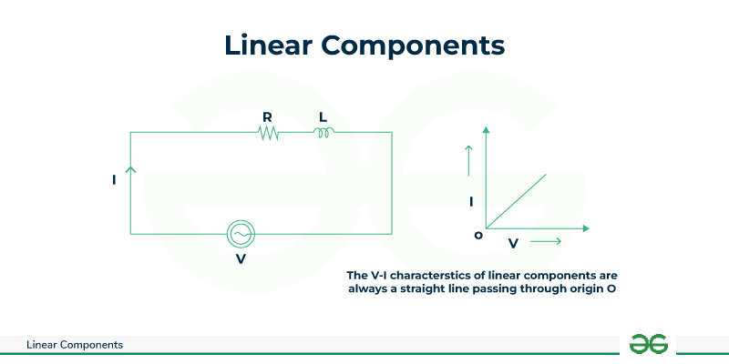
In Electrical Circuits, Linear components refer to the components in an electrical circuit that exhibit a linear relationship between the current input and the voltage output.
An component is said to be linear, where V-I characteristics follow only one equation of the straight line passing through the origin all the time. Linear Components are those whose characteristics are straight lines passing through the origin. Linear Components do not require any external power supply to operate in the electrical circuit. Linear Components receive the electrical energy and either convert it or store it in the form of a magnetic field or electric field. Linear Components are important because they can amplify and process electronic signals without distortion.
In linear circuits, these linear elements is also known as electrical elements in the electric circuit and there will be a linear relationship between the voltage and current. The main examples of the Linear Components in electrical circuits are resistors, capacitors ,inductors, transformers, etc.
Working of Linear Components
Linear Components are those, where V-I characteristics follows only one equation of straight line passing through origin for all the time. Linear Components are those that characteristics are straight line and passing through the origin.
Working of Linear Components include, these Linear circuit elements follows ohm’s law:
Ohm’s Law: The potential difference in volts V, across the terminals of a given metallic wire in an electric circuit is directly proportional to the current flowing I through it, given its temperature remains the same.
This is known as Ohm’s law. In other words, it can be written as: Potential difference across the ends ∝ Current
or
V ∝ I
The Linear Components which obeys ohm’s law is resistor, capacitor, inductor, transformer and many other components.
Linear-Components
Types of Linear Components in Electrical Circuits
In electrical circuits, Linear Components are mainly divided into four basic electronic components which include:
- Resistor
- Capacitor
- Inductor
- Transformer
Resistors
Resistors control the flow of current by offering resistance. They are used to limit current, divide voltage, and set biasing conditions in electronic circuits.
- Resistors oppose the flow of electrical charge or electrical current.
- Resistance is measured in ohm.
- The opposition to the flow of electrical current through the material is known as the resistance of that material.
- Resistors are made up of materials like Tungsten, Bronze, and Constantan.
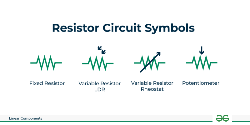
Resistor-Circuit-Symbols
Resistor voltage equation:
V= I x R
- where V stands for Voltage
- I stands for Current
- R stands for Resistance

Resistor
Advantages of Resistor
- It is used to control voltage and current in electrical circuit.
- Low cost.
- It Provide precise resistance value
- Widely available in Market.
Disadvantages of Resistor
- It produces heat when current flow in it.
- It does not store energy.
Applications of Resistor
There are many applications of linear components like resistors which include:
- It is used in Potential Divider.
- It helps in Biasing Circuits.
- It is used in Feedback Networks.
- It is used in Amplifiers.
- It is used in Current controlling devices.
- It is used in Coupling Networks.
- It is used in DC Power Supplies.
V-I Characteristics of a Resistor
- V-I Characteristics of a resistor can be explained by the relation between the applied voltages and the current flowing through it
- From Ohm’s law, we know that when the voltage applied across the resistor increases, the current flowing through it also increases i.e. the voltage applied is directly proportional to current.

V-I-Characteristics-of-a-Resistor
Capacitors
Capacitors store and release electrical energy. They are commonly used for decoupling, filtering, and energy storage in electronic circuits.
- It is used to pass AC and block DC.
- It opposes the flow of direct current.
- It consists of two conducting parallel plates separated by dielectric.
- Dielectric is made up of ceramic, mica, glass, waxed paper, and bakelite.

Capacitor Circuit Symbol
Capacitor current equation with respect to time:
[Tex]I(t) = C \frac{dV(t)}{dt}
[/Tex]
- I(t) stands for current in capacitor with respect to time
- C stands for capacitance
- V(t) stand for voltage across the capacitor with respect to time t.
.png)
Capacitor
Advantages of Capacitor
- It stores electrical energy in it.
- It is used in timing circuits.
- It is used to stabilize voltage in circuit.
Disadvantages of Capacitor
- it stores limited energy only.
- It may leak its charge over time.
Applications of Capacitor
There are many applications of linear components like capacitors which include:
- It is used for storage of energy.
- It is used in filter circuits to minimize the repel voltage.
- It is used in tunning circuits for selection of frequency.
- It is used in timing circuits to select the time.
- It is used in Amplifiers.
V-I Characteristics of Capacitor
- V-I Characteristics of a capacitor can be explained by the relation between the applied voltages and the current flowing through it
- From Ohm’s law, we know that when the voltage applied across the resistor increases, the current flowing through it also increases i.e. the voltage applied is directly proportional to current.
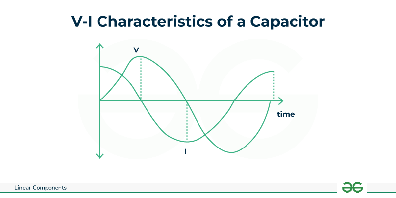
VI Characteristics-of-Capacitor
Inductors
Inductors store and release magnetic energy. They are used for applications such as filtering, energy storage, and impedance matching.
- All inductors are coiled structures and insulated wire wrapped around the area.
- Inductors work on electromagnetic induction.
- It is used to decrease the electric spikes in electronic circuits.

Inductor
Inductor Current equation with respect to time:
V(t) = [Tex]
V(t) = L\frac{di(t)}{dt}
[/Tex]
- V(t) stand for voltage across the inductor with respect to time t
- L stands for inductance
- i(t) stand for current through the inductor with respect to time t
.png)
Inductor
Advantages of Inductor
- It stores electrical energy in it.
- It is used in transformers.
- It is used to stabilize voltage in circuit.
Disadvantages of Inductor
- It can be heavy.
- It causes voltage spikes when current in the circuit changes.
Applications of Inductors
There are many applications of linear components like inductors which include:
- It is used in minimizing alternating current in the circuits.
- It is used in RF choke in the oscillator.
- It is used in LC resonance.
- It is used in Radio Transmitter and receiver.
V-I Characteristics of Inductor
- V-I Characteristics of a inductor can be explained by the relation between the applied voltages and the current flowing through it
- The amount of voltage that will be produced in an inductor depends on how rapidly the current through it will decrease. The induced voltage will be opposed to the change in current as described by Lenz’s Law. The voltage polarity will be oriented to keep the current at its former magnitude with a decreasing current. As shown in the image below, the amount of induced voltage produced by the inductor depends upon the rate of current change

V-I-Characteristics-of-a-Inductor
A transformer is also a passive electronic component. A transformer is used to transfer electrical power from one circuit to another via magnetic media i.e. magnetic core.
- It has two windings on a core. The winding to which input power is given is called the primary winding.
- The winding which delivers power to the load is the secondary winding.
- When transformers step up or step down voltage, power, and energy remain the same on the primary and secondary sides. As energy is not being amplified.
- Transformers are often used to raise voltage levels and keep the power constant.

Transformer-Circuit-Symbol
Transformer current Equation
[Tex]\frac{I1}{I2} =\frac{N2}{N1}
[/Tex]
- I1 stands for primary current in transformer
- I2 stands for primary current in transformer
- N1 stands for number of turns in primary winding
- N2 stands for number of turns in secondary winding

Transformer
Advantages of Transformer
- It is used in changing the voltage.
- It offers isolation between input and output in circuits.
Disadvantages of Transformer
- It can be heavy
- It is only limited to AC circuits.
Applications of Transformers
- It is used to raise voltage levels.
- It is used in power generation
- It is used in transmission and distribution.
- It is used in lighting, audio systems, and electronic equipment.
V-I characteristics of Transformer
- V-I Characteristics of a Transformer can be explained by the relation between the applied voltages and the current flowing through it
- From Ohm’s law, we know that when the voltage applied across the resistor increases, the current flowing through it also increases i.e. the voltage applied is directly proportional to current.
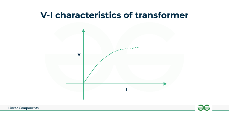
VI-characteristics-of-Transformer
Other Linear components in electrical circuits include controllers, sensors, diodes, thermistors, varactors, transducers, and many other common components. These components follows ohms law. These components are available as through-hole and components, and many are available in common packages with standard land patterns.
VI Characteristics of Linear components in Electrical Circuits
The V-I characteristics of a circuit stand for the Voltage-Current characteristics of a circuit. The graph of current and voltage is drawn on the graph to show how one changes when a change in the other is done. The slope of this graph gives resistance, but only in the case when the slope is linear. Does that mean non-linear graphs of V-I characteristics are present too? YES. There are both linear and non-linear graphs. However, if non-linear graphs exist, ohms law would not have been valid. Ohms law exists and so does the non-linear graph.
- The reason behind this so-called contradiction is simple. Although Ohms law is applicable and true for a lot of materials, it is not applicable for some materials where the law of proportionality does not work. Let’s learn about each one of the graphs in detail,
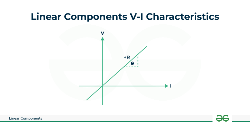
Linear Components V-I Characteristics
Linear Components V-I characteristics are shown by ohmic resistors. Ohms law talks about the relation between voltage and current where it tells that the voltage and current are proportional to each other, therefore, if a graph is drawn, a straight line is obtained. The slope of the line gives resistance. Higher the slope, the higher will be the resistance. Hence,
R = [Tex]\frac{\Delta V}{\Delta I}
[/Tex]and R = tanθ
The V-I characteristics give a straight line passing through the origin. In a resistance, if the voltage polarity is reversed, the current will start to flow opposite direction with equal magnitude if the magnitude of the voltage is not altered.
Linear-Components-V-I-Characteristics
Difference between linear and non linear components
Linear Components
| Non Linear Components
|
|---|
In linear circuit, the components like (resistance, inductance, capacitance, transformers, etc.) are always constant and does not change irrespective of variations in current or voltage.
| In non-linear circuit, the components like diodes ,transistors, etc. change with voltage or current.
|
Ohm’s law is applicable for linear components.
| Ohm’s law is not applicable for non-linear components.
|
For every input signal level, a straight line will appear on a graph of a linear circuit’s output signal vs input signal.
| For every input signal level, a straight line will appear on a graph of a linear circuit’s output signal vs input signal.
|
For every input signal level, a straight line will appear on a graph of a linear circuit components output signal vs input signal.
| In a nonlinear circuit components, the output will not be a straight line. Instead, the output will be a curve.
|
Linear Components require an external power supply to operate.
| Non linear Components do not require external power supply to operate
|
Examples of linear components are resistors, inductors, capacitors, transformers etc.
| Examples of non-linear components are diodes, transformers, transistors, etc.
|
Conclusion
In this article we have learnt about Linear components, these can easily handle energy in the electrical circuit by storing it in the form of a magnetic or electric field or converting it into some other form of energy. We have seen the properties of Linear components and different types of linear components and we have the applications and advantages and disadvantages of linear components. In electrical circuits, Linear components play an important role in storing and handling energy in the electrical circuits.
FAQs On Linear Components
Q1. How can we identify the component is an linear component in electrical circuits?
We can identify the component is an linear component (such as resistance, capacitance, inductance, gain, etc.) when it does not change the value with the level of voltage or current applied in the circuit.
Q2. What is the classification of linear components in electrical circuits?
The classification of components, which do not change with the level of voltage or current in the circuit. are called components . Resistors, capacitors, inductors, transformers, etc. are classified into linear components in electrical circuits.
Q3. What are linear components and non linear circuit components in electrical circuits?
Linear Circuit Components are the components that shows a linear relationship between voltage and current. Examples: Resistors, Inductors, capacitors ,Transformers ,etc. Non-Linear Circuit Components are those that do not show a linear relation between voltage and current. Examples: Voltage sources and current sources.
Q4. Is transistor a Linear Component?
No, transistor is not a Linear Component. Unlike resistors, which has a linear relationship between voltage and current, transistors are non-linear components. They have four distinct modes of operation, which describe the current flowing through them.
Share your thoughts in the comments
Please Login to comment...