Full Adder in Digital Logic
Last Updated :
07 Aug, 2023
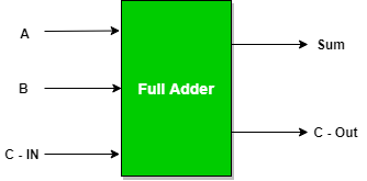
Full Adder is the adder that adds three inputs and produces two outputs. The first two inputs are A and B and the third input is an input carry as C-IN. The output carry is designated as C-OUT and the normal output is designated as S which is SUM. The C-OUT is also known as the majority 1’s detector, whose output goes high when more than one input is high. A full adder logic is designed in such a manner that can take eight inputs together to create a byte-wide adder and cascade the carry bit from one adder to another. we use a full adder because when a carry-in bit is available, another 1-bit adder must be used since a 1-bit half-adder does not take a carry-in bit. A 1-bit full adder adds three operands and generates 2-bit results.
 Full Adder Truth Table:
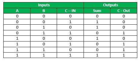
Logical Expression for SUM: = A’ B’ C-IN + A’ B C-IN’ + A B’ C-IN’ + A B C-IN = C-IN (A’ B’ + A B) + C-IN’ (A’ B + A B’) = C-IN XOR (A XOR B) = (1,2,4,7)
Logical Expression for C-OUT: = A’ B C-IN + A B’ C-IN + A B C-IN’ + A B C-IN = A B + B C-IN + A C-IN = (3,5,6,7)
Another form in which C-OUT can be implemented: = A B + A C-IN + B C-IN (A + A’) = A B C-IN + A B + A C-IN + A’ B C-IN = A B (1 +C-IN) + A C-IN + A’ B C-IN = A B + A C-IN + A’ B C-IN = A B + A C-IN (B + B’) + A’ B C-IN = A B C-IN + A B + A B’ C-IN + A’ B C-IN = A B (C-IN + 1) + A B’ C-IN + A’ B C-IN = A B + A B’ C-IN + A’ B C-IN = AB + C-IN (A’ B + A B’)
Therefore COUT = AB + C-IN (A EX – OR B)
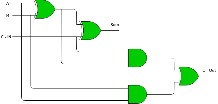
Full Adder logic circuit.
Implementation of Full Adder using Half Adders:
2 Half Adders and an OR gate is required to implement a Full Adder.
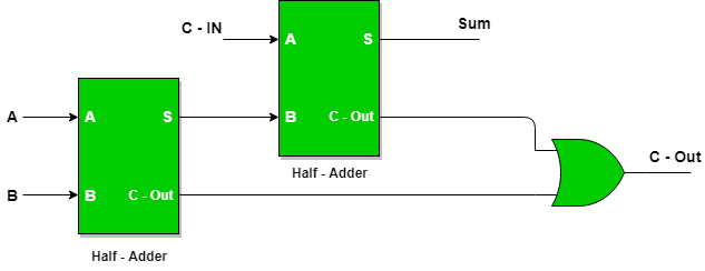
With this logic circuit, two bits can be added together, taking a carry from the next lower order of magnitude, and sending a carry to the next higher order of magnitude.
Implementation of Full Adder using NAND gates:  Implementation of Full Adder using NOR gates:
Total 9 NOR gates are required to implement a Full Adder.  In the logic expression above, one would recognize the logic expressions of a 1-bit half-adder. A 1-bit full adder can be accomplished by cascading two 1-bit half adders.
Advantages and Disadvantages of Full Adder in Digital Logic
Advantages of Full Adder in Digital Logic:
1.Flexibility: A full snake can add three information bits, making it more flexible than a half viper. It can likewise be utilized to add multi-bit numbers by binding different full adders together.
2.Carry Info: The full viper has a convey input, which permits it to perform expansion of multi-bit numbers and to chain different adders together.
3.Speed: The full snake works at an extremely fast, making it reasonable for use in rapid computerized circuits.
Disadvantages of Full Adder in Digital Logic:
1.Complexity: The full snake is more mind boggling than a half viper and requires more parts like XOR, AND, or potentially entryways. It is likewise more challenging to execute and plan.
2.Propagation Deferral: The full viper circuit has a proliferation delay, which is the time it takes for the result to change in light of an adjustment of the info. This can cause timing issues in computerized circuits, particularly in fast frameworks.
Application of Full Adder in Digital Logic:
1.Arithmetic circuits: Full adders are utilized in math circuits to add twofold numbers. At the point when different full adders are associated in a chain, they can add multi-bit paired numbers.
2.Data handling: Full adders are utilized in information handling applications like advanced signal handling, information encryption, and mistake rectification.
3.Counters: Full adders are utilized in counters to addition or decrement the count by one.
4.Multiplexers and demultiplexers: Full adders are utilized in multiplexers and demultiplexers to choose and course information.
5.Memory tending to: Full adders are utilized in memory addressing circuits to produce the location of a particular memory area.
6.ALUs: Full adders are a fundamental part of Number juggling Rationale Units (ALUs) utilized in chip and computerized signal processors.
Share your thoughts in the comments
Please Login to comment...