Adders and Subtractors in Digital Logic
Last Updated :
21 Jun, 2022
Subtraction of two binary numbers can be accomplished by adding 2’s complement of the subtrahend to the minuend and disregarding the final carry if any. If the MSB bit in the result of addition is a ‘0’. then the result of addition is the correct answer. If the MSB bit is a ‘1’. , this implies that the answer has a negative sign. The true magnitude, in this case, is given by 2’s complement of the result of the addition.
Block Diagram of Combinational Logic Circuit: 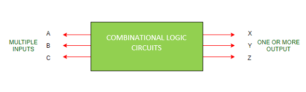
Points to Remember on Combinational Logic Circuit:
- Output depends upon the combination of inputs.
- Output is a pure function of present inputs only i.e., Previous State inputs won’t have any effect on the output. Also, It doesn’t use memory.
- In other words,
OUTPUT=f(INPUT)
- Inputs are called Excitation from circuits and outputs are called Responses of combinational logic circuits.
Classification of Combinational Logic Circuits:
1. Arithmetic:
- Adders
- Subtractors
- Multipliers
- Comparators
2. Data Handling:
- Multiplexers
- DeMultiplexers
- Encoders and Decoders
3. Code Converters:
- BCD to Excess-3 code and vice versa
- BCD to Gray code and vice versa
- Seven Segment
Design of Half Adders and Full Adders:
- A combinational logic circuit that performs the addition of two single bits is called Half Adder.
- A combinational logic circuit that performs the addition of three single bits is called Full Adder.
1. Half Adder:
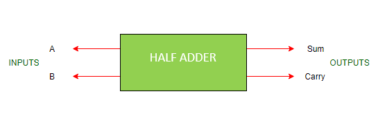
- It is a arithmetic combinational logic circuit designed to perform addition of two single bits.
- It contain two inputs and produces two outputs.
- Inputs are called Augend and Added bits and Outputs are called Sum and Carry.
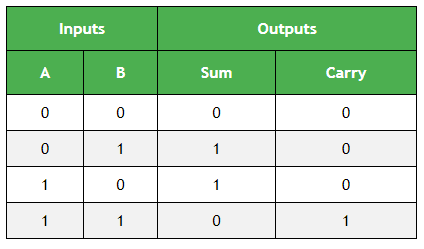
Let us observe the addition of single bits,
0+0=0
0+1=1
1+0=1
1+1=10
Since 1+1=10, the result must be two bit output. So, Above can be rewritten as,
0+0=00
0+1=01
1+0=01
1+1=10
The result of 1+1 is 10, where ‘1’ is carry-output (Cout) and ‘0’ is Sum-output (Normal Output).
Truth Table of Half Adder:
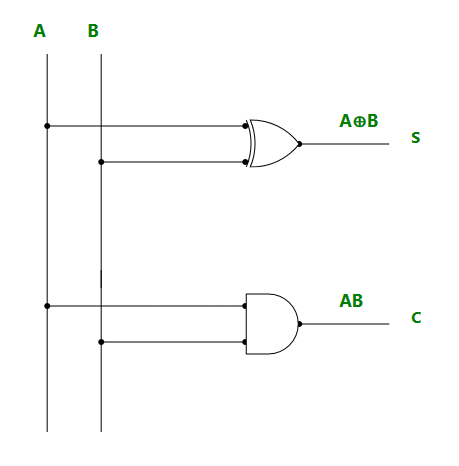
Next Step is to draw the Logic Diagram. To draw Logic Diagram, We need Boolean Expression, which can be obtained using K-map (karnaugh map). Since there are two output variables ‘S’ and ‘C’, we need to define K-map for each output variable.
K-map for output variable Sum ‘S’:
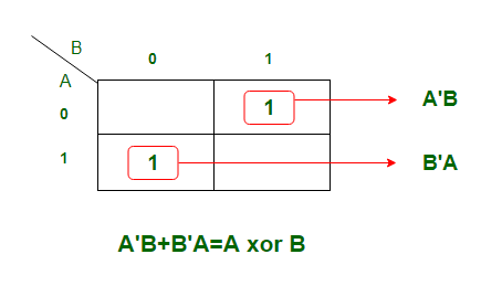
K-map is of Sum of products form. The equation obtained is
S = AB' + A'B
which can be logically written as,
S = A xor B
K-map for output variable Carry ‘C’:
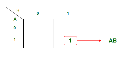
The equation obtained from K-map is,
C = AB
Using the Boolean Expression, we can draw logic diagram as follows..
Limitations: Adding of Carry is not possible in Half adder.
2. Full Adder:
- To overcome the above limitation faced with Half adders, Full Adders are implemented.
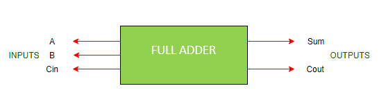
- It is a arithmetic combinational logic circuit that performs addition of three single bits.
- It contains three inputs (A, B, Cin) and produces two outputs (Sum and Cout).
- Where, Cin -> Carry In and Cout -> Carry Out
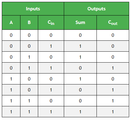
Truth table of Full Adder:
K-map Simplification for output variable Sum ‘S’ : 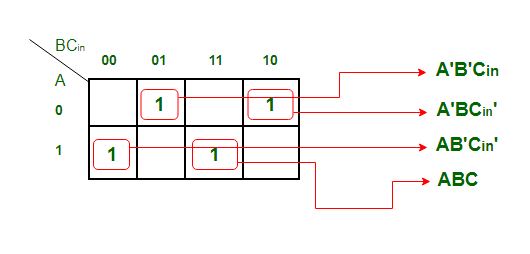
The equation obtained is,
S = A'B'Cin + AB'Cin' + ABC + A'BCin'
The equation can be simplified as,
S = B'(A'Cin+ACin') + B(AC + A'Cin')
S = B'(A xor Cin) + B (A xor Cin)'
S = A xor B xor Cin
K-map Simplification for output variable ‘Cout‘
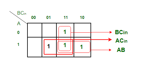
The equation obtained is,
Cout = BCin + AB + ACin
Logic Diagram of Full Adder: 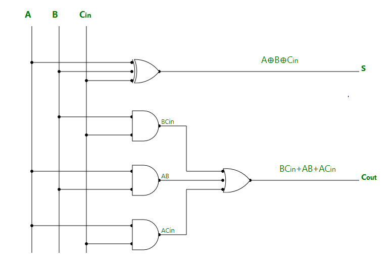
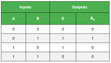
3. Half Subtractor:
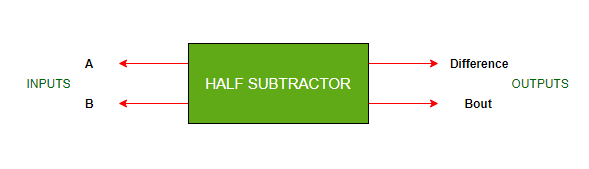
- It is a combinational logic circuit designed to perform the subtraction of two single bits.
- It contains two inputs (A and B) and produces two outputs (Difference and Borrow-output).
Truth Table of Half Subtractor:
K-map Simplification for output variable ‘D’:
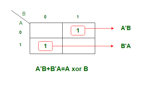
The equation obtained is,
D = A'B + AB'
which can be logically written as,
D = A xor B
K-map Simplification for output variable ‘Bout‘ :
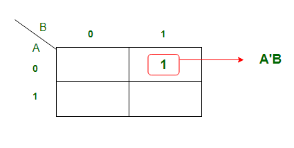
The equation obtained from above K-map is,
Bout = A'B
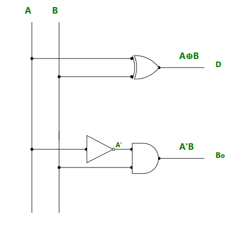
Logic Diagram of Half Subtractor:
4. Full Subtractor:
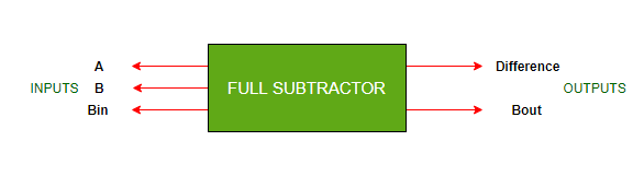
- It is a Combinational logic circuit designed to perform subtraction of three single bits.
- It contains three inputs(A, B, Bin) and produces two outputs (D, Bout).
- Where, A and B are called Minuend and Subtrahend bits.
- And, Bin -> Borrow-In and Bout -> Borrow-Out
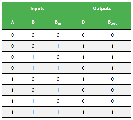
Truth Table of Full Subtractor:
K-map Simplification for output variable ‘D’ : 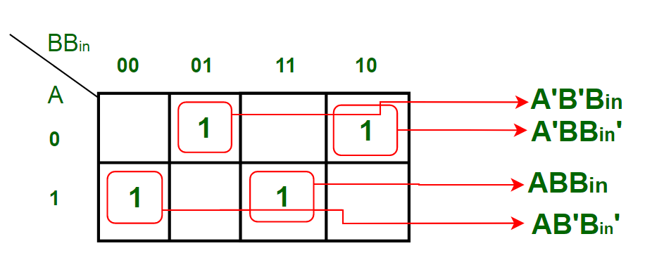 The equation obtained from above K-map is,
D = A'B'Bin + AB'Bin' + ABBin + A'BBin'
which can be simplified as,
D = B'(A'Bin + ABin') + B(ABin + A'Bin')
D = B'(A xor Bin) + B(A xor Bin)'
D = A xor B xor Bin
K-map Simplification for output variable ‘Bout‘ : 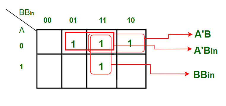
The equation obtained is,
Bout = BBin + A'B + A'Bin
Logic Diagram of Full Subtractor: 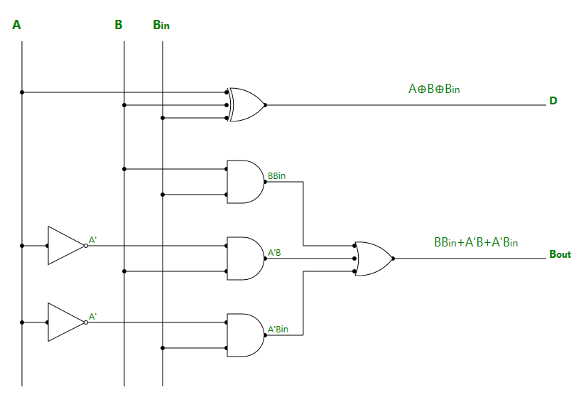 Applications:
- For performing arithmetic calculations in electronic calculators and other digital devices.
- In Timers and Program Counters.
- Useful in Digital Signal Processing.
Share your thoughts in the comments
Please Login to comment...