Implementation of Full Adder Using Half Adders
Last Updated :
25 Apr, 2024
Implementation of full adder from half adders is possible because the half adders add two 1-bit inputs in full adder we add three 1-bit inputs. To obtain a full adder from a half adder we take the first two inputs and add them and use the sum and carry outputs and the third input to get the final sum and carry output of the full adder. In this article, we will explore half adders, and full adders and implement full adders using half adders.
What is Half Adder?
Half adder is a combinational circuit that is used to add two 1-bit inputs to generate two outputs sum and carry. The sum in half adder is given by XORing both the inputs. The carry in the half adder is given by the product of both inputs. Half Adders are used in the Various Digital Systems Where Addition of Binary Numbers is Required Such as Arithmetic Circuits, Digital Calculators, Microcontrollers and Processors, Communication systems and Control Systems.
Expression for Sum in Half Adder
From the above truth table, the expression for sum S in half adder is:
S = A ⊕ B
where,
A and B are inputs and ⊕ represents XOR operation
Expression for Carry in Half Adder
From the above truth table, the expression for carry C in half adder is:
C = AB
Logic Diagram for Half Adder
To implement half adder, we require one XOR gate and one AND gate. Below is the logic diagram for half adder.

Half Adder
Block Diagram for Half Adder
Below is the block diagram for half adder.

Block Diagram of half Adder
What is Full Adder?
Full adder is a combinational circuit that is used to add three 1-bit inputs to generate two outputs sum and carry. The sum in full adder is given by XORing all the inputs. The carry in the full adder is given by sum of product of two inputs. Full Adders are important component in digital Circuit and are used in the ALUs (Arithmetic Logic Units),Binary Additions, Address decoding, Counters and Registers, Data Encryption and Decryption and Digital Signal Processing.
Expression for Sum in Full Adder
From the above truth table, the expression for sum S in half adder is:
S = A ⊕ B ⊕ C
where,
A, B and C are inputs and ⊕ represents XOR operation.
Expression for Carry in Full Adder
From the above truth table, the expression for carry in half adder is:
Carry = AB + BC + AC
Logic Diagram for Full Adder
To implement full adder, we require 2 XOR gate, 2 AND gate and 1 OR gate. Below is the logic diagram for full adder.
.png)
Full Adder
Block Diagram for Full Adder
Below is the block diagram for full adder :
Implementation of Full Adder Using Half Adders
Below is the logic diagram to implement full adder using half adders
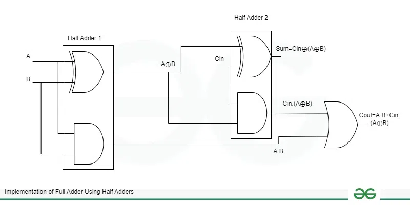
logic diagram of Full Adder From half Adder
Steps to Implement Full Adder from Half Adders
Steps to implement full adder from half adders in above logic diagram :
- First connect first two input with first XOR gate and first AND gate which outputs A ⊕ B and AB respectively.
- Then, connect the third input and output of first XOR gate [i.e., A ⊕ B]as input to second XOR gate which results in the sum of full adder [i.e., A ⊕ B ⊕ C].
- Then, connect the output of first XOR gate [i.e., A ⊕ B] and third input C as the input to second AND gate [i.e., (A ⊕ B)C].
- After that connect the output of first AND gate [i.e., AB] and output of second AND gate [i.e., (A ⊕ B)C] as the input to OR gate which results in the carry of full adder i.e., AB + AC + BC.
- Since, we require 1 XOR and 1 AND gate to implement half adder and in above diagram we used 2 XOR gate, 2 AND gate and 1 OR gate.
- From above point we get that to implement full adder using half adders we require 2 half adders and 1 OR gate.
Below is the block diagram to implement full adder using half adders.

block diagram to implement full adder using half adders
Steps to implement full adder from half adders in above block diagram :
- Connect first two inputs as the input of first half adder which results in two outputs sum and carry.
- Then, connect sum output of first half adder and third input as input to second half adder.
- Then, connect carry output of the first half adder and carry output of second half adder to OR gate.
- The sum output of second half adder gives us the sum of full adder.
- The output of the OR gate gives us the carry of full adder.
- Hence, to implement full adder using half adders, two half adders and one OR gate is required.
Conclusion
From the above discussion we can conclude that to implement full adder from half adders we require two half adders. In first half adder we connect two inputs and generate sum and carry. After that we connect sum of first half adder and third input as the input of the second half adder which results in the sum output as sum of full adder. After that we connect carry output of second half adder and carry of first half adder as input to OR gate which results in the carry of full adder.
Implementation of Full Adder Using Half Adders – FAQs
What is Full Adder?
The combinational circuit that is used to add three 1-bit inputs is called as full adder.
What is the Expression for Sum in Half Adder?
The expression for sum in half adder is:
S = A ⊕ B
What is the Expression for Carry in Full Adder?
The expression for carry in full adder is:
Carry = AB + AC + BC
How Many Half Adders are Required to Implement Full Adder?
To implement full adder using half adders we require two half adders.
Share your thoughts in the comments
Please Login to comment...