A single-phase induction motor is a small-size motor with a fractional-kilowatt rating. They work on the principle of electromagnetic induction to create a rotating magnetic field. It is used in domestic appliances like fans, hair dryers, washing machines, vacuum cleaners, mixers, refrigerators, food processors and kitchen equipment employ these motors.
Single Phase Induction Motor
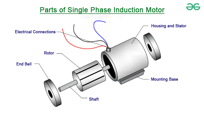
Construction of Single-Phase Induction Motor
To construct Single Phase Induction Motor, it comprises of two major components which is the rotor and the stator.
Stator: As the name implies, a stator is a stationary component of an induction motor. The stator of a single phase induction motor receives a single phase alternating current source.
Rotor: The rotor is a rotating component of an induction motor. The rotor transmits mechanical load via the shaft. The squirrel cage rotor is used in the single-phase induction motor.
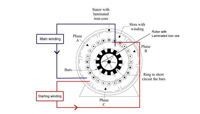
Construction of Single Phase Induction Motor
The design of a single phase induction motor is quite similar to that of a squirrel cage three-phase induction motor. A single phase induction motor, on the other hand, contains two windings instead of one three-phase winding in a three phase induction motor.
Components of Single-Phase Induction Motor
A single-phase induction motor consists of several key components:
1. Stator of Single Phase Induction Motor
The stator is the stationary part of the motor and contains the primary winding and an auxiliary winding. The main winding is designed to produce a magnetic field when an AC voltage is applied. The auxiliary winding, found in motors, provides a phase shift to create a rotating magnetic field. When a single phase AC supply is applied to the stator winding, the magnetic field is generated, and the motor starts rotating at a speed slightly less than the synchronous speed Ns. Synchronous speed Ns is given by:
[Tex]N_{s} = \frac{120f}{P}
[/Tex]
Where,
f = supply voltage frequency
P = No. of poles of the motor.
The construction of the single-phase induction motor’s stator is similar to that of the three-phase induction motor, with the exception of two differences in the winding component of the single phase induction motor.
- Single phase induction motor are provided with concentric circle. We can easily adjust the number of turns per coil can with the help of concentric coils.
- Asynchronous motors, with the exception of shaded pole motors, have two stator windings: the primary winding and the auxiliary winding. These two windings are in spatial quadrature to one another.
2. Rotor of Single Phase Induction Motor
The rotor is the rotating part of the motor. In single-phase induction motors, the rotor is made up of a squirrel-cage consists of conductive bars embedded in slots around in rotor’s periphery. These bars are short-circuited at both ends by end rings. When the rotating magnetic field from the stator cuts across the squirrel cage bars, it induces currents, generating a magnetic field in the rotor that interacts with the stator’s field and produces rotation.
These rotor conductors are braced to the end ring to provide mechanical strength, forming a complete closed circuit resembling a cage, hence the name squirrel cage induction motor. Because the end rings permanently short the bars, the rotor electrical resistance is very low, and adding external resistance is not conceivable because the bars are constantly shorted. The lack of a slip ring and brushes simplifies and strengthens the construction of a single phase induction motor.
3. Bearings of Single Phase Induction Motor
Bearings are used to support and allow the rotor to rotate within the stator. It reduces friction.
Note: These components work together to create the necessary magnetic field and currents, enabling the single-phase induction to start and run.
Operation and Working of Single-Phase Induction Motor
A single-phase induction motor is similar in construction to that of a polyphase induction motor with the difference that its stator has only one winding. When a single phase AC supply is applied to the stator winding of single phase induction motor, the alternating current starts flowing through the stator or main winding. The flux is then generated by the AC current. The flux also links with the rotor conductors and hence cut the conductors of the rotors.
According to the Faraday’s law of electromagnetic induction, emf gets induced in the rotor. The current begins to flow in the rotor after the rotor circuit is closed. The flux created by this rotor current is known as the rotor flux. Since this flux is produced due to the induction principle so, the motor working on this principle got its name as an induction motor. There are currently two fluxes: the main flux and the rotor flux. The desired torque, which the motor needs to rotate, is produced by these two fluxes.
Its motors consist of a single-phase winding mounted on the stator and a cage winding on the rotor. When a single-phase supply connected to stator winding pulsating magnetic field is produced. Under these conditions, the rotor does not rotate. It requires some special starting methods.
Why Single Phase Induction Motor is not Self Starting?
A single-phase induction motor lacks a naturally rotating magnetic field, which makes it non-self-starting. Unlike three-phase motors that generate a rotating magnetic field with three alternating currents, single-phase motors rely on a single alternating current that produces a pulsating magnetic field. This field is unable to initiate continuous rotation in the motor’s rotor due to its non-uniform nature and inability to provide sufficient starting torque.
At the starting condition of the motor, both φf (forwarding component of alternating flux(φm)) and φb(backward component of alternating flux(φm)) are equal in magnitude but opposite in direction. They cancel each other out, which results zero net torque on the rotor. This zero torque at the starting condition is why single-phase induction motors are not self-starting.
To overcome this limitation, various techniques are used, such as adding an auxiliary winding and a capacitor to simulate a rotating magnetic field during startup or using centrifugal switches to disconnect the starting winding once the motor reaches a certain speed. These methods help single-phase induction motors achieve the necessary torque for self-starting and sustained operation.
Starting Methods and Types of Single-Phase Induction Motor
- Split-phase motor
- Capacitor-start motor
- Capacitor-start capacitor-run motor (or two-value capacitor motor)
- Permanent-split capacitor (PSC) motor (or single-value capacitor motor)
- Shaded-pole motor
1. Split-Phase Induction Motor
It is also called a resistance start motor. It has a single-cage rotor and its stator has two windings- a main winding and a starting (auxiliary) winding which is displaced 90° in space. The main winding has very low resistance and high inductive reactance.
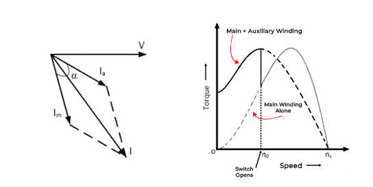
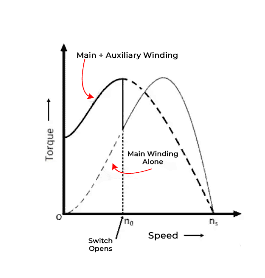
The torque-speed characteristics of the motor.
The starting winding has a resistance connected in series with it. It has high resistance and low inductive reactance. Auxiliary winding current I(a) is nearly in phase with the line voltage. There is a time phase difference between the currents in the two winding usually of the order of 30°. which is enough to produce a rotating magnetic field. Since the current in two winding is not the same the rotating magnetic field is non-uniform and the starting torque is small as of the order of 1.5 to 2 times the rated running torque.
During starting the main and auxiliary windings are connected in parallel. When the motor reaches the speed of about 70 to 80 percent of synchronous speed the starting winding is disconnected from the supply automatically. For motors rated about 100W or more, a centrifugally operated switch is used to disconnect the starting winding.
The relay is connected in series with the main winding. At the time of starting, a heavy current flows in the relay coil causing its contact to close. As the motor reaches its predetermined speed of the order of 70 to 80 percent of the synchronous speed the current through the relay coil decreases. Consequently, the relay opens and disconnects the auxiliary winding from the main supply and the motor then runs only on the main winding.
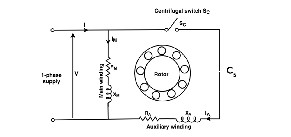
2. Capacitor-Start Motor
It has a cage rotor and its stator has two winding (main winding and auxiliary winding) which are displaced 90° in space. The capacitor Cs is connected in series with starting windings. The centrifugal switch Sc is also connected.
Capacitor-Start Motor
By choosing the capacitor of proper rating the current I(M) in the main winding may be made to lag the current in IA in the auxiliary winding by 90°. Thus, a single-phase supply current is split into two phases to be applied to the stator windings. The windings MMFs are equal in magnitude but 90° apart in time phase. Therefore, the motor acts like a balanced two-phase motor. As the motor approaches its rated speed, the auxiliary winding and the starting capacitor Cs are disconnected automatically by the centrifugal switch Sc mounted on the shaft.
3. Capacitor-Start Capacitor-Run Motor (Two Value Capacitor Motor):-
It has a cage rotor and its stator has two windings (main winding and auxiliary winding) displaced by 90° in space. The motor uses two capacitors Cs (starting capacitor) and CR (run capacitor). The two capacitors are connected in parallel at the start. To obtain a high starting torque, a large current is required therefore the capacitive reactance X in the starting torque should be low. For this Cs should be large ([Tex]X_{A} = \frac{1}{2\Pi fCA}
[/Tex]).
.png)
Capacitor-Start Capacitor-Run Motor
During normal operation, the rated line current is smaller than the starting current. Hence the capacitive reactance should be large. For this CR should be small ([Tex]X_{R} = \frac{1}{2\Pi fCR}
[/Tex]). As the motor approaches synchronous speed, the capacitor Cs is disconnected by a centrifugal switch SC. The capacitor CR is permanently connected to the circuit. Since the capacitor Cs is used only at starting and the other CR for continuous running, this motor is also called a capacitor-start capacitor-run motor.
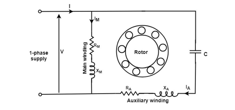
4. Permanent-Split Capacitor (PSC) Motor
It is also known as a single-value capacitor motor. It has a cage rotor and its stator has two windings (the main winding and the auxiliary winding). The motor uses one capacitor C connected in series with the starting winding. The capacitor C is permanently connected in the circuit both at starting and running conditions. Since the capacitor C is always in the starting, this type of motor has no starting switch. The auxiliary winding is always in the circuit; therefore, this motor operates in the same way as a balanced two-phase motor. Consequently, it produces a uniform torque.
Permanent-Split Capacitor (PSC) Motor
5. Shaded Pole Motor
A shaded pole motor is a single-phase induction motor that is typically seen in tiny appliances and low-power applications. The shading coils, which are copper or aluminium rings or bands wrapped around a portion of the motor’s pole pieces (thus “shaded” poles), give it its name. These shading coils are critical to the motor’s functionality.
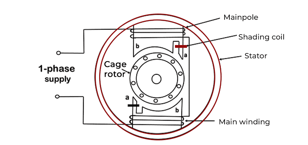
Shaded Pole Motor
Key Characteristics and Principle of Single-Phase Induction Motor
1. Single-Phase Induction Motor
Shaded pole motors are a form of induction motor that operates on a single phase. Single-phase motors are commonly employed in applications where three-phase electricity is unavailable or not required.
2. Starting Mechanism
Unlike capacitors or centrifugal switches found in other single-phase motors, shaded pole motors lack a standard starting mechanism. Instead, they use the phase shifting principle to generate a rotating magnetic field.
3. Operating Principle
When a shaded pole motor is powered up, the shading coils cause a phase shift in the magnetic field produced by the main winding. This phase shift generates a spinning magnetic field, which causes the rotor (the shaded pole) to begin revolving.
4. Low Starting Torque
Shaded pole motors are known for their low starting torque, making them ideal for applications where the load is relatively steady and considerable starting power is not required. They are unsuitable for applications that require strong starting torque, such as heavy machinery.
5. Applications
It is used in small domestic equipment which includes fans, refrigerators, ovens, and some types of pumps. They are also utilized in various HVAC (heating, ventilation, and air conditioning) components and applications where low temperatures are required.
Equivalent Circuit Of Single-Phase Induction Motor
The equivalent circuit of a single-phase induction motor can be obtained by either double-field revolving theory or cross-field theory. Equivalent circuit of a single-phase induction motor based on two revolving field theories. Most single-phase induction motors are two-phase motors in which auxiliary winding is disconnected from the supply when the machine reaches a certain value.
Let us develop the equivalent circuit of a single-phase induction motor running on its main winding M. Consider a case when the rotor is stationary and only the main winding is excited with its secondary short-circuited.
- A single-phase induction motor behaves as a single-phase transformer when the secondary is short-circuited.
- The core loss of the branch is not considered, only the mechanical and stray losses are considered as the rotational losses of the motor.
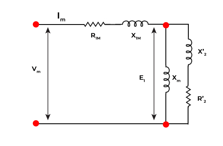
Here,
- R1m = resistance of the main stator winding.
- X1m = leakage reactance of the main stator winding.
- XM = magnetizing reactance.
- R2‘ = standstill rotor resistance referred to the main stator winding.
- X2‘ = standstill rotor leakage reactance referred to the main stator winding.
- Vm = applied voltage
- ImI’mSimplicity = main winding current.
The pulsating air-gap flux of the motor at a standstill can be resolved into two equal and opposite fluxes with the motor. The magnitude of each rotating flux is one-half of the alternating flux. Each phase possesses reactive and resistive voltage drops in the rotor circuit.
The standstill impedance of each rotor referred to the main stator winding
if ([Tex]\frac{R2′}{2} + \frac{jX2′}{2}
[/Tex]).
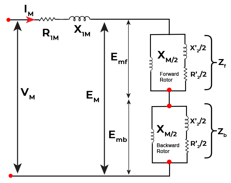
The forward flux induces the voltage Emf and the backward flux induces a voltage Emb. So, the resultant voltage in the main winding is given by,
Em = Emf + Emb
- When the motor is at a standstill, Emf = Emb. Therefore both rotors will have the same slip under this condition.
The motor is started with the help of auxiliary winding and after some time it is disconnected from the circuit.
The effective rotor resistance of the induction motor depends on the amount of relative motion between the rotor and the stator magnetic field. Two magnetic fields exist, one is rotating in a clockwise direction and the other is rotating in an anti-clockwise direction.
Slip of the rotor:-
- w.r.t forward rotating flux = s
- w.r.t backward rotating flux = 2-s
Effective rotor resistance with the forward magnetic field will be = [Tex]\frac{R2′}{2s}
[/Tex]
Effective rotor resistance with the backward magnetic field will be = [Tex]\frac{R2′}{2(2-s)}
[/Tex]
Rotor impedance offered to the forward field, Zf = ( [Tex]\frac{R2′}{2s}
[/Tex] +[Tex] \frac{jX2′}{2}
[/Tex]) || ([Tex]\frac{jXm}{2}
[/Tex])
= ([Tex]\frac{R2′}{2s}
[/Tex] + [Tex] \frac{jX2′}{2}
[/Tex])([Tex]\frac{jXm}{2}
[/Tex])/([Tex]\frac{R2′}{2s}
[/Tex] + [Tex] \frac{jX2′}{2}
[/Tex] + [Tex]\frac{jXm}{2}
[/Tex])
Rotor impedance offered to the backward field, Zb = ([Tex]\frac{R2′}{2(2-s)}
[/Tex] + [Tex] \frac{jX2′}{2}
[/Tex]) || ([Tex]\frac{jXm}{2}
[/Tex])
= ([Tex]\frac{R2′}{2(2-s)}
[/Tex] +[Tex] \frac{jX2′}{2}
[/Tex]([Tex]\frac{jXm}{2}
[/Tex])/([Tex]\frac{R2′}{2s}
[/Tex] + [Tex] \frac{jX2′}{2}
[/Tex] + [Tex]\frac{jXm}{2}
[/Tex])
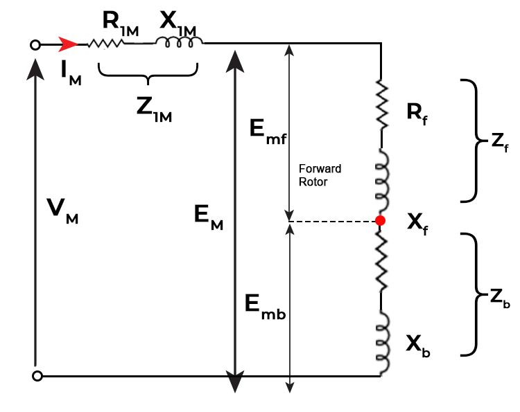
The current in the stator winding is, Im = [Tex]\frac {Vm}{Z_{1m} + Z_{f} + Z_{b}}
[/Tex]
Determination of Equivalent Circuit Parameters
The parameters of the equivalent circuit of a single phase induction can be determined from:-
- Blocked-rotor test
- No-load test
Blocked-rotor test
In this, the rotor is at rest. A low voltage is applied to the stator so that rated current flows in the main winding. The voltage, current, and power input are measured.
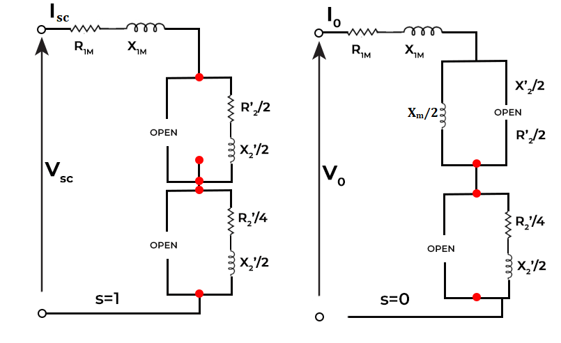
Simplified equivalent circuit of single induction motor with locked rotor and at no load
- Ze = [Tex]\frac{V_{sc}} {I_{sc}}
[/Tex]
Equivalent series resistance Re of the motor, Re = [Tex]\frac{P_{sc}}{I_{sc}^{2}}
[/Tex]
Equivalent reactance, Xe = X1m + X2‘
Since leakage reactances X1m and X2‘ cannot be separated therefore, X1m = X2‘
- X1m = 0.5 * (Ze2 – Re2)1/2
No-Load Test
The motor is run without load at rated voltage and rated frequency.
At no load, the slip ‘s’ is very close to zero and [Tex]\frac{R2′}{2s}
[/Tex] is very large as compared to [Tex]\frac{X_{M}}{2}
[/Tex].
The resistance [Tex]\frac{R2′}{2(2-s)}
[/Tex]associated with the backward field is so small as compared to [Tex]\frac{X_{M}}{2}
[/Tex].
- X0 = X1m + [Tex]\frac{X_{M}}{2}
[/Tex] + X2‘
Since X1m and X2‘ are already known from the blocked rotor test.
Let V0, I0, the denote and P0 denote the voltage, current, and power at the no-load test. Then no-load power factor is
- cosΦ0 = [Tex]\frac{P_{0}}{V_{0}I_{0}}
[/Tex]
The no-load impedance is, Z0 = V0/I0
The no-load equivalent reactance is,
X0 = Z0 sinΦ0 = Z0 x (1 – cos2 Φ0 )
Comparison between Single Phase and Three Phase Induction Motor
Single Phase Induction Motor
| Three Phase Induction Motor
|
|---|
Easy to build and cost effective for small power ratings
| Complex to build and costly for small power ratings
|
It has lower electrical power factor
| It has more electrical power factor as compared to single phase induction motor.
|
It provides 50% less power than three phase induction motor.
| It provides more output power.
|
It s less efficient
| It is more efficient
|
The starting torque is low.
| Starting torque is high.
|
Application of Single-Phase Induction Motor
Single-phase induction motors are widely used in various applications due to their simplicity, cost-effectiveness, and ease of operation. They are commonly used in situations where a three-phase power supply is not available or practical. Here are some common applications of single-phase induction motors:
- Household Appliances.
- Pumps.
- Compressors.
- Blowers.
- Food Processors.
Advantages of Single-Phase Induction Motor
- Simplicity: Single-phase, induction motors are simpler in construction compared to three-phase induction motors, resulting in lower manufacturing costs.
- Suitable for residential use: They are commonly used in household appliances like fans, blowers.
- Cost-effective: Single phase motors are generally less expensive to purchase and maintain Single-phase.
- Availability: They are widely available and come in various sizes and power ratings to meet different requirements.
Disadvantages of Single-Phase Induction Motor
- Lower efficiency: Single-phase motors have lower efficiency compared to three-phase motors, which results in higher energy consumption.
- Lower Starting Torque: They tend to have lower starting torque, which might limit their use in applications requiring a high starting load.
- Limited Power Range: They are not as suitable for high-power applications as three-phase motors, since three-phase motors can provide more consistent power output.
Solved examples on Single-Phase Induction Motor
Q 1. A 230V, 50Hz, 4-pole single phase induction motor has the following equivalent circuit impedances :
R1m = 2.2 Ω, R2‘ = 4.5 Ω, X1m = 3.1 Ω, X2‘ = 2.6 Ω, XM = 80Ω
Friction, windage and core loss = 40W
For a slip of 0.03 pu , calculate
- input current
- power factor
- developed power
- output power
- efficiency
Solution:
[Tex]\frac{R2′}{2s}
[/Tex]= [Tex]\frac{4.5}{2*0.03}
[/Tex] = 75 Ω .
[Tex]\frac{R2′}{2(2-s)}
[/Tex]= [Tex]\frac{4.5}{2*(2-0.03)}
[/Tex] = 1.142 Ω
[Tex]\frac{1}{2X2′}
[/Tex]= [Tex]\frac{1}{2*2.6}
[/Tex] = 1.3 Ω
[Tex]\frac{1}{2X_{M}}
[/Tex]= 1/2 *80 = 40 Ω
For the forward field circuit,
Zf = Rf + jXf = ([Tex]\frac{R2′}{2s}
[/Tex] + [Tex] \frac{jX2′}{2}
[/Tex])([Tex]\frac{jXm}{2}
[/Tex])/([Tex]\frac{R2′}{2s}
[/Tex] + [Tex] \frac{jX2′}{2}
[/Tex] + [Tex]\frac{jXm}{2}
[/Tex])
= ( (75+j1.3)(j40) )/( 75+j1.3+j40 ) = 16.37 + j 30.98 Ω
For the backward field,
Zb = Rb + j Xb = ([Tex]\frac{R2′}{2(2-s)}
[/Tex] +[Tex] \frac{jX2′}{2}
[/Tex]([Tex]\frac{jXm}{2}
[/Tex])/([Tex]\frac{R2′}{2s}
[/Tex] + [Tex] \frac{jX2′}{2}
[/Tex] + [Tex]\frac{jXm}{2}
[/Tex])
= ( 1.142 + j 1.3 )( j 40 ) / ( 1.142 + j 1.3 + j 40)
= 2.2 + j 3.1 Ω
The total series impedance
Zc = Z1m + Zf + Zb
= 2.2 + j 3.1 + j 16.37 + j 30.98 + 1.07 + j 1.29
= 19.64 + j 35.37
(a) Input Current
Im = Vm/Zc = -1.68 + j 5.42 A
(b) Power factor = cos( -60.95 ) = 0.4856 lagging
(c) Developed power
Pconv = Pd = Im2 (Rf-Rb)(1-s)
= (5.685)(16.37-1.07)(1-0.03)= 479.65 W
(d) Output power = Pd – Prvt
= 479.65-40 = 439.65 W
Input power = VIm cosΦ = 230 * 5.685 * 0.4856 = 634.9 W
(e) Efficiency = output/input = 439.65 / 634.9 = 0.692 pu.
Q 2. A 220 V, single-phase induction motor gave the following results:
Blocked-rotor test: 120 V, 9.6 A, 460 W
No-load test: 220 V ,4.6 A, 125 W
The stator winding resistance is 15 Ω, and during the blocked-rotor test, the starting winding is open. Determine the equivalent circuit parameters. Also, find the core friction and windage losses.
Solution:
Blocked-rotor test,
Vsc = 120V, Isc = 9.6A , Psc = 460W
Ze = Vsc/Isc = 120/9.6 = 12.5 Ω
Re = Psc/I2sc = 460/(9.6)2 = 4.99 Ω.
Xe = ( Ze2-Re2 )1/2 = ( (12.5)2 – (4.99)2 )1/2 = 11.46 Ω
X1m = X2‘ = 1/2 Xe = 1/2*11.46 = 5.73 Ω
R1m = 1.5 Ω
Re = R1m + R2‘
R2‘ = Re – R1m = 4.99 – 1.5 = 3.49 Ω
No-load power factor,
cos Φ = Po/VoIo = 125/220*4.6 = 0.1235
sin Φ = 0.9923
Zo = Vo/Io = 220/4.6 = 47.83 Ω
Xo = Zo sin Φ = 47.83*0.9923 = 47.46 Ω
Core, friction and windage losses
= power input to the motor at no load – no load copper loss
= Po – Io2 ( R1m + R2‘/4 )
= 125 – (4.6)2 ( 1.5 + 3.49/4 ) = 74.8 W
Q 3. A 6-pole, 50 Hz, 3-phase induction motor has a rotor resistance of 0.25 W per phase and a maximum torque of 10 Nm at 875 rpm. Calculate
(a) the torque when the slip is 5%, and (b) the resistance
to be added to the rotor circuit to obtain 60% of the maximum torque at starting. The stator impedance is assumed to be negligible.
Solution:
ns = [Tex]\frac{ 120*50}{6}
[/Tex]= 1000 rpm
ws = [Tex]\frac{2π*1000}{60 }
[/Tex]= 104.7 rad/s
smax = [Tex]\frac{ 1000 – 875 }{1000}
[/Tex] = 0.125
X2 = R2 / smax = 0.25/0.125 = 2 Ω
Tmax = [Tex]\frac{3}{ ws} *\frac{ 0.5 V_{2} }{ X_{2′}}
[/Tex]
10 = [Tex]\frac{3}{104.7}* \frac{ 0.5 V_{2}}{X_{2}’}
[/Tex]
V’ = V/a = (1396)2 V
s = 0.05
T = 6.9 Nm
[Tex]\frac{T_{start}}{T_{max}}
[/Tex] = (R2 + Rext) / ((R2 +Rext)2) + X2 ) x (X2/0.5)
Rext = 4.417 Ω
FAQs on Single-Phase Induction Motor
1. Why do some single-phase motors require capacitors, and role of capacitor in motor operation?
Capacitors are used to create a phase shift in the windings, which helps start and run the motor. Start capacitors are used primarily for starting, while run capacitors assist in maintaining a constant speed and power factor during operation.
2. Can a single-phase induction motor be used for to produce high-torque ?
Single-phase induction motors are not able to produce high-torque because of their limited starting torque.
3. What are the challenges faced while in reversing the direction of rotation of a single-phase motor with a capacitor?
Reversing the direction of a single-phase motor with a capacitor is a challenging task because it requires reconfiguration of capacitor connections. It may also require changes to the rotor or the capacitor value, depending on the motor design.
Share your thoughts in the comments
Please Login to comment...