The primary objective of a single phase inverter is to generate an AC output waveform that ideally replicates a sinusoidal pattern with minimal harmonic content. This sinusoidal waveform closely resembles the standard AC electricity supplied by utility grids. The importance of achieving a high-quality sinusoidal waveform cannot be overstated. It serves to mitigate harmonic distortion, ensuring the proper functioning of a wide array of loads, including sensitive electronic equipment and electric motors. By minimizing the harmonic content, single-phase inverters contribute to the overall stability and reliability of electrical systems. The ability to produce a clean sinusoidal waveform enables these inverters to meet the stringent requirements of modern electrical devices ultimately, facilitating the seamless integration of DC and AC power source. Some industrial applications of inverters are for adjustable-speed AC drives, induction heating, stand by air-craft power supplies, UPS for computers, HVDC transmission lines, etc.
Here in this article, we will discuss types of single phase inverters, and their essential parts, applications, advantages, and disadvantages. Single phase inverters are ideal for use in home appliances, power tools, office equipment, water pumping in agriculture, adjustable speed ac drives, induction heating, vehicles UPS, and grid connected applications.
Single Phase Inverter
A single-phase inverter is a type of inverter that converts DC source voltage into single-phase AC output voltage at a desired voltage and frequency and it is used to generate AC Output waveform means converting DC Input to AC output through the process of switching. Phase-commutated inverters when operated in the inverter mode , are called line-commutated inverters . But line-commutated inverters require at the output terminals an existing ac supply which used for their commutation.
Key Components of a Single-Phase Inverter
- DC Source: DC source is the input of the inverter in which the battery or solar panel ,etc. are used as the input term to be used.
- Control Unit: Most of the time microcontroller is used in this as a device which is used to control the switching sequence of the circuit in order to produce the AC output.
- Filter : This is the output filter which is used to smoothen the output waveform specially in case of sine waves and pure sine waves inverter.
- Inverter Circuit: A circuit which is used to convert the specified voltage or frequency range with the combining of converter and inverter, it consist of electric switches such as thyristors and transistors.
Types of Single-Phase Inverter
Single phase inverters are classified into two types. They are :
- Half bridge inverter
- Full bridge inverter
Basically there are three types of waveform of the single phase inverter:
- Square wave inverter
- Modified Sine wave inverter
- Pure sine wave inverter
Half Bridge Inverter
The half bridge inverter architecture serves as a fundamental building block in the realm of single phase inverters, offering a straight forward structure that efficiently converts direct current into alternating current . This configuration consists of two switch components often transistors, IGBT’s , MOSFET’s arranged in series across a DC voltage source . Additionally , two feedback diodes and two capacitors establish connections between the source and load . In this setup , the load is strategically positioned between the midpoint of the capacitors and the midpoint of the diodes and switches. Through complementary switching operations of the components , an alternating current output voltage is generated across the load. Feedback diodes come into play particularly with inductive loads, ensuring a smooth and controlled current flow.
Half Bridge Inverter with Resistive Load
The circuit given below is a single phase inverter with resistive load where RL is resistive load , Vs/2 is taken as the voltage source and self commutating switches S1 and S2 , each is connected in parallel with diodes D1 and D2. S1 conducts when the voltage is positive and current is negative , while S2 conducts when both voltage and current are negative . Diode D1 conducts during positive voltage and negative current , whereas diode D2 conducts during negative voltage and positive current . This configuration ensures a continuous current flow through the load. The self-commutating nature of the switches allows for precise control, enabling S1 and S2 to alternate conduction based on voltage and current polarities . Overall , this design facilitates efficient conversion of the DC input into AC output, making it suitable for various applications , especially where resistive-inductive load are involved.
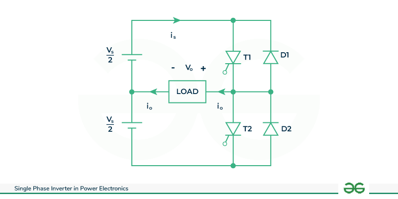
Half Bridge Inverter with Resistive Load
Case 1 : When switch S1 is ON from 0 to T/2 time period, then diode D1 and D2 are reverse biased and switch S2 is OFF.
By applying Kirchhoff’s voltage law ,
Output voltage V0 = Vs/2 Output current i0 = V0/ R = Vs/2R
If switch current is1 = i0 = Vs/2R , is2 = 0 and also the diode current
id1 = id2 = 0
Case 2 : when switch S2 is ON from T/2 to T time period , then diode D1 and D2 are reverse biased and switch S1 is OFF .
By applying Kirchhoff’s voltage law ,
Output voltage V0 = -Vs /2
Output current i0 = V0/R = -Vs/2R
If switch current is1 = 0, is2 = -Vs/2R and also the diode current
iD1 = iD2 = 0
Half Bridge Inverter with Resistive Load
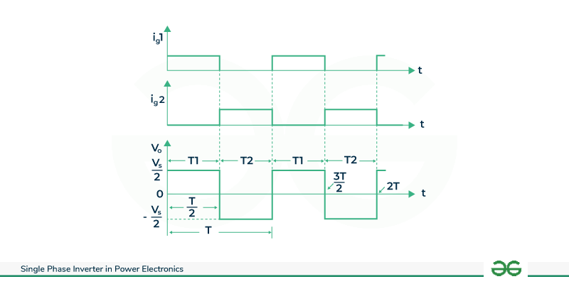
These voltage waveforms are drawn on the assumption that each thyristor conducts for the duration its gate pulse is present and is commutated as soon as this pulse is removed . It is seen that for 0< t <= T/2 , SCR T1 conducts and the load is subjected to a voltage Vs/2 due to upper voltage source . At t=T/2 , SCR T1 is commutated and T2 is gated on . During the period T/2 < t <T , SCR T2
conducts and the load is subjected to a voltage -Vs/2 due to the lower voltage source. It is seen that load voltage is an alternating voltage waveform of amplitude Vs/2 and of frequency 1/T Hz . Frequency of the inverter output voltage can be changed by controlling T .
Half Bridge Inverter with R-L Load
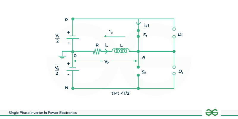
The single phase half-bridge inverter circuit comprises essential components, including two switches , two diodes and a voltage supply . The R-L load is positioned between two points A and O , with A denoting the positive terminal and O representing the negative terminal . Current direction is defined such that when flowing from A to O , it is considered positive, and conversely , when flowing from O to A , it is treated as negative. The switches control the flow of current through the load , enabling the inverter to alternate the polarity of the output . This alternating current facilitates the conversation of direct current from the supply into an alternating current across the load , essential for various applications such as motor drives and power electronics . The diodes play a crucial role in providing a return path for the inductive components , ensuring the smooth operation of the circuit .
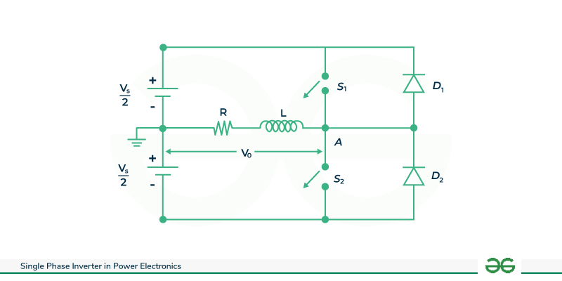
Half Bridge Inverter with RL load
Case 1 (0 < t < t1) : In this time period , both the switches S1 and S2 are OFF and diode D2 is in reverse bias condition . During this period , the inductor releases its energy through diode D1 then output current decreases exponentially from negative peak value to zero. V0 = Vs/2. By applying Kirchhoff’s voltage law
Output voltage V0 > 0Output current i0 < 0Switch current is1 = 0Diode current id2 = -i0
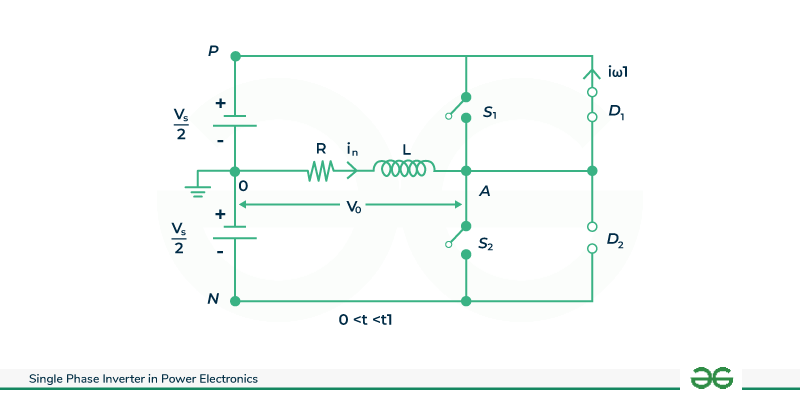
0 < t < t1
Case 2 (t1 < t < T/2) : In this time period , switch S1 is closed and S2 is OFF and both the diodes are in reverse biased condition . In this period inductor starts to store the energy , and output current increases from zero to its positive peak value . Vo = Vs/2 .By applying Kirchhoff’s voltage law.
Output voltage V0 > 0Output current i0 > 0Switch current is1 = i0Diode current id1 = 0
t1 < t < T/2
Case 3 (T/2 < t < t2) : In this time period , both the switches S1 and S2 are OFF , diode D1 is reverse biased and diode D2 id reverse biased. In this period inductor releases its energy through diode D2 and the output current decreases exponentially from its positive peak value to zero . V0 = -Vs/2 . By applying Kirchhoff’s voltage law.
Output voltage V0 < 0Output current i0 > 0Switch current is1 = 0Diode current id1 = 0
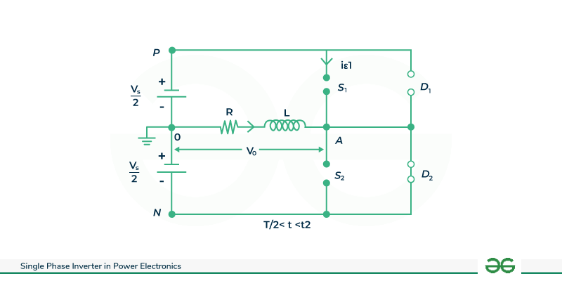
T/2 < t < t2
Case 4 (t2 < t < T) : In this time period , switch S1 is OFF and S2 is closed , diode D1 and D2 are reverse biased . In this period , the inductor charged to negative peak value to zero . V0 = Vs/2 . By applying Kirchhoff’s voltage law.
Output voltage V0 < 0Output current i0 < 0Switch current is1 = 0Diode current id1 = 0
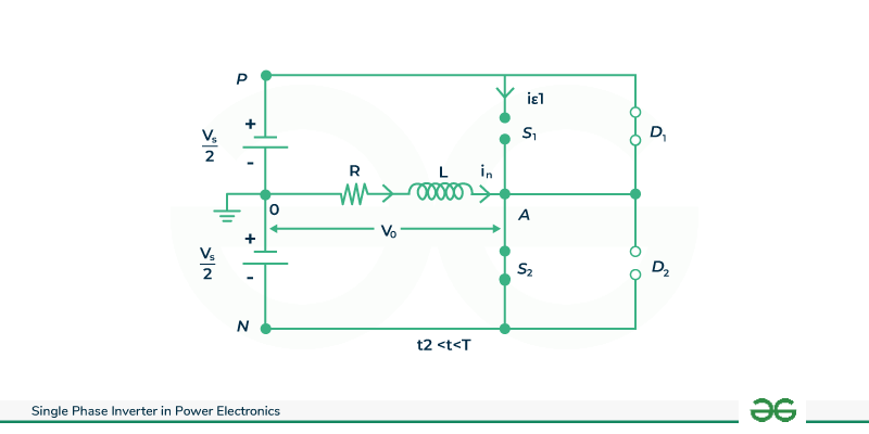
t2 < t < T
Full Bridge Inverter
A full-bridge inverter is a type of H-bridge inverter employed for converting DC power into AC power . In contrast to single-phase half-bridge inverters, it utilizes twice the number of components . The circuit comprises four diodes and four controlled switches, often thyristors. These switches, which can be BJT , IGBT , MOSFET or thyristors , play a crucial role in the inversion process. The power circuit of a single phase full bridge inverter is constructed with precision, featuring four thyristors labeled T1 to T4 , four diodes D1 to D4 and a two wire DC input power source denoted as Vs . The four diodes , also known as freewheeling or feedback diodes, facilitate the redirection of stored energy in the load back to the DC source , particularly beneficial for non-pure resistive loads. This feedback mechanism enhances efficiency and stability . The full-bridge inverter configuration provides versatility in adapting to various applications and load types , making it a widely utilized topology in DC to AC power conversion systems . The diodes are strategically placed in antiparallel configuration with the thyristors ; for instance , D1 is connected in antiparallel with T1 and similarly for the rest . These diodes are known as freewheeling diodes or feedback diodes because these The circuit is designed to facilitate the conversion of direct current from the input source into alternating current for various applications .
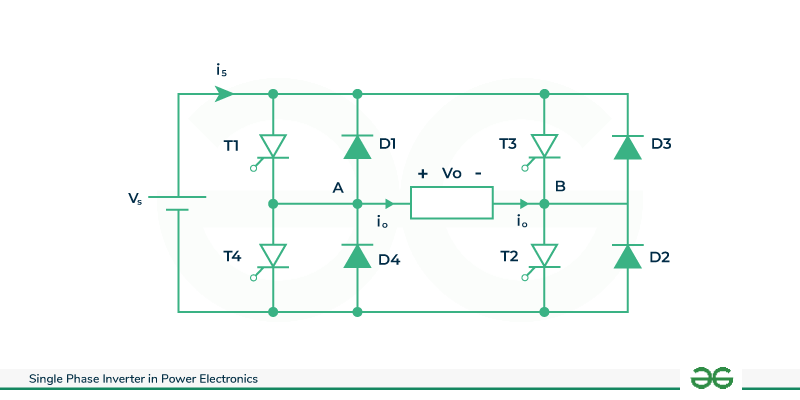
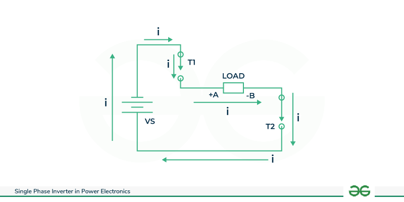
Full bridge inverter circuit
Case1 (T1 and T2 are ON) : The depicted circuit operates with transistors T1 and T2 in the conducting state while T3 and T4 remain non-conductive . Assuming a current “i” flowing from point A to B , the current path traverses points A – B – C- D .Consequently , T1 and T2 act as a short circuit , facilitating the flow of current in this direction . The output voltage is positive at point A with respect to B . Upon examination of the circuit , it is evident that the supply voltage is directly connected to the load terminal , resulting in a short circuit . This implies that the supplied voltage , denoted as +Vs , will instantaneously appear across the load terminal . The current convention , assuming it flows from A to B , deems the output current positive . In essence , the output voltage +Vs , reflecting the direct supply connection to the load terminal . This design ensures that any input voltage is immediately across the load , simplifying analysis by employing an equivalent circuit that highlights the short circuit condition .In the time period (0<t<= T/2) , thyristors T1 and T2 conducts and load voltage V0 = Vs.
Full Bridge Inverter
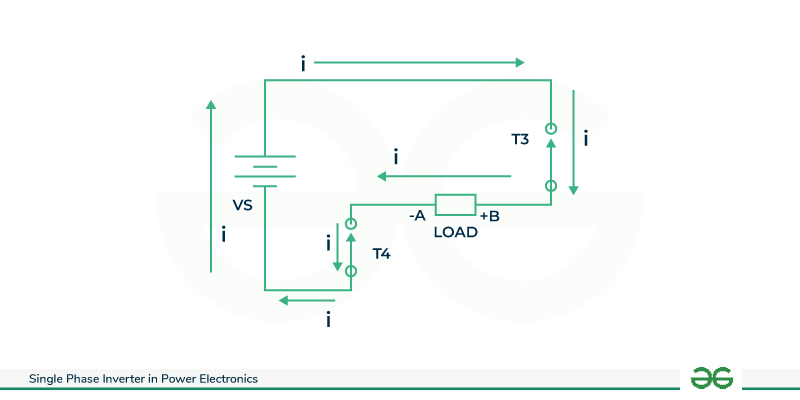
Case 2 ( T3 and T4 are ON ) : Assuming switches T3 and T4 are ON and T2 and T2 are turned off so the circuit is as shown below . Switches T3 and T4 are short circuited and current starts flowing through the supply from here (a – b- c- d-e -f) and returns to the source . In this configuration , the output current is considered negative as it flows from point B to A , aligning with our established convention. Consequently , the output voltage is also negative. The supplied voltage , +Vs is directly connected to point B , yielding a positive potential , while the negative terminal is directly linked to point A , resulting in a negative potential . Thus the output voltage is -Vs. To comprehend the DC to AC conversion process, a focus on waveform is essential triggering of transistors T1 and T2 initiates the pulse generation . T1 and T2 remain on for a specified duration, directing current from point A to B . Subsequently , T3 and T4 are triggered, allowing T1 and T2 to turn off . This sequential operation prevents simultaneous conduction , averting a short circuit . Analyzing the pulses and timings of T1/T2 and T3/T4 reveals the transformation of DC to AC , providing insight into the circuit’s functionality and ensuring optimal performance without compromising the supply integrity . In the time period (T/2)<t<= T , thyristors T3 and T4 conducts and the load voltage V0 = -Vs .
Full Bridge Inverter
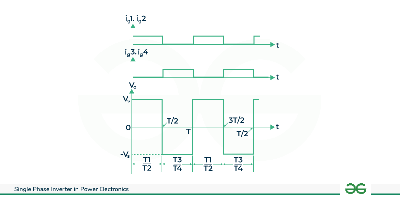
Here , it is seen that for 0 < t <= T/2 , SCR s T1 , T2 conduct and the load is subjected to a voltage Vs . At t= T/2 , SCRs T1 , T2 are commutated and T3 , T4 are gated on . During the period T/2 < t <= T , SCRs T3 , T4 conduct and the load is subjected to a voltage -Vs . It is seen that load voltage is an alternating voltage waveform of amplitude Vs and of frequency 1/T Hz . Frequency of the inverter output voltage can be changed by controlling T . From the above waveform , we can observe that the direction of current flowing through the load in mode 1 (0<= t <=T/2) is opposite to the current flowing through mode 2 (T/2 < =t <=T ). Thus an alternating output is obtained at the output side from a DC power . Whereas when an inductive load is connected to the inverter , the load current lags behind the load voltage .The function of the diodes is to feed the reactive power back to the source provided by the load is inductive . If the load is purely resistive reactive power will be zero and hence the need for diodes is eliminated .
Full bridge inverter
Advantages of Single-Phase Inverters
- Single phase inverters are generally simpler and more cost effective to design and implement compared to three phase inverters .
- Due to their simplicity , single phase inverters are often easier to install and maintain , making them more accessible for individuals with limited technical expertise.
- Many household appliances and devices operate on single-phase power. Single-phase inverters are seamlessly integrate with these loads without requiring additional equipment for compatibility .
- Single-phase inverters are suitable for a wide range applications, including solar power systems and small scale renewable energy projects .
- There is minimal fluctuation of voltage in the circuit .
- These are suitable for high input voltage .
Disadvantages of Single-Phase Inverters
- Single-phase inverters are may exhibit lower power quality compared to three-phase system .
- Single-phase inverters may experience more pronounced voltage imbalances affecting the stability of the power supply .
- Single-phase inverters are typically limited in terms of the power they can handle . In high power capacities cases , three phase inverters are more suitable.
- The efficiency of full bridge inverter is less than the half bridge inverter .
- There are more losses and noise are high , so it requires more switching elements .
Applications of Single-Phase Inverters
- Single phase inverters are commonly used in residential solar power systems to convert DC electricity generated by solar panels into AC electricity for use in homes.
- These are employed in ups systems to provide a backup power source during a electrical outages . They convert DC power from batteries into AC power to keep critical equipment running seamlessly .
- Heating , ventilation and air conditioning systems often use single phase inverters to control the speed of motors , providing efficient energy and variable speed operation .
- Single phase inverters plays a crucial a role in emergency lighting systems , ensuring that essential lights remain operational during power failures .
- Apart from residential solar applications , single phase inverters are used in small scale wind and hydroelectric power systems to convert generated DC power into grid compatible AC power .
Solved Examples on Single-Phase Inverters
Q. The single phase half bridge inverter has a resistive load of R=1.2ohms and the DC input voltage is 24V . Determine
- RMS output voltage at the fundamental frequency
- Output power
- Average thyristor current
- Peak thyristor current
Given that R= 1.2ohms , input voltage (Vs) = 24v
RMS output voltage at the fundamental frequency is V01 = (2Vs/pi)/√2
V01 = (2*24/pi)/√2
V01 =10.803v
Output power P0 = (V0rms)2/R
=(Vs/2)2/ R
=(24/2)2/1.2
=120
Average thyristor current = It1 = It2 = ([Vs/2R]*[T/2])/T
=([24/2*1.2]*[T/2])/T
=5 A
Peak thyristor current = It1 peak = It2 peak = (Vs/2*R)
=24/(2*1.2)
=10
Conclusion
In conclusion, the single-phase inverter serves as a fundamental component in converting DC power to AC power , finding widespread use in various applications . Its simplicity and cost-effectiveness make it suitable for small-scale systems , residential solar inverters and portable electronic devices . With a circuit typically composed of a single pair of controlled switches and two diodes , it efficiently transforms direct current into alternating current for powering single-phase loads . despite it’s advantages , such as ease of implementation and reduced component count , single-phase inverters may face limitations in handling larger power requirements or three-phase loads . As technology advances, the single-phase inverter continues to evolve , balancing simplicity with the demand for higher efficiency and expanded functionality in modern energy conversion systems .
FAQs on Single-Phase Inverters
What are the classification of single phase inverters ?
There are two types of single phase inverters : half bridge inverter and full bridge inverter
What is the efficiency of single phase inverters ?
High quality sine wave inverters are 90%-95% efficient whereas low quality modified sine wave inverters are 70%- 75% efficient.
Can a single phase inverters can be used in three phase systems?
Generally , it is not recommended to use single phase inverter in case of three phase systems as it may lead to imbalance and inefficiency in the power distribution .
Share your thoughts in the comments
Please Login to comment...