What are the Control Methods in Power Electronics ?
Last Updated :
13 Dec, 2023
In this composition we will learn about Control styles in power electronics, The Control styles in power electronics are abecedarian ways used to manage and regulate the inflow of electrical energy in electronic systems. These styles play a pivotal part in ensuring effective and dependable operation of the power electronic bias.
What is Control Methods in Power Electronics?
The Control styles in power electronics relate to the ways and strategies used to manage and regulate the inflow of electrical energy within the electronic systems. These styles are employed to control the geste of the power electronic bias is icing they operate efficiently, reliably, and according to asked specifications. The primary thing of the control style is to manipulate the electrical power in a way that meets specific conditions similar to voltage regulation, current control, and overall system stability.
Key Terminologies Related to Control Methods
- Power Electronics : The operation of electronics principles for control and conversion of electric power.
- PWM : A system used to render analog information in the digital signals by varying the palpitation range of the fixed-frequent square surge.
- Feedback Control : A control system strategy that uses feedback from affairs to regulate the input is icing the asked affair.
- Hysteresis Control : A control system that prevents rapid-fire changes in the system by introducing the dead band or hysteresis.
- Voltage Regulation : The process of maintaining a stable affair voltage by conforming the input to power electronic device.
Control Methods in Power Electronics
- Pulse Width Modulation (PWM)
- Feedback Control
- Hysteresis Control
- Time Ratio Control
- Current Limit Control
Pulse Width Modulation (PWM)
.png)
Pulse Width Modulation (PWM)
The PWM is a widely used technique to control the average power delivered to load by the varying the duty cycle of the fixed-frequency pulse signal. It is commonly employed in the applications like motor control voltage regulation and inverters.
Working Principle of PWM
- Pulse Generation: The PWM generates a series of the pulses with fixed frequency. The duration of the each pulse known as the pulse width is variable.
- Control Signal: The width of the pulses is controlled by the reference signal often called the modulation or control signal.
- Duty Cycle: The duty cycle is the ratio of the pulse width to total time period of the one cycle. It is usually expressed as a percentage.
Duty Cycle (%) = (Pulse Width Total Time Period) × 100 Duty Cycle (%)=( Total Time Period Pulse Width )×100
- Average Voltage Control: By varying the duty cycle the average voltage applied to load can be controlled. A higher duty cycle results in the higher average voltage and vice versa.
Feedback Control
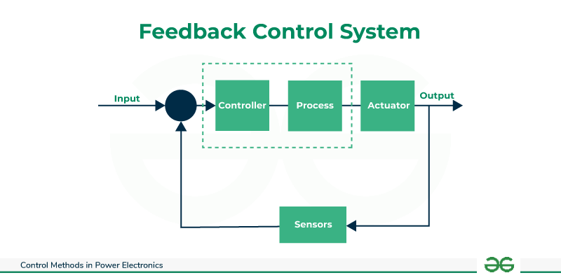
Feedback Control System
The Feedback control systems continuously monitor the output and adjust the input to maintain the desired output. The Proportional-Integral-Derivative (PID) controllers are commonly used for the feedback control in the power electronics.
Working of a Feedback Control System
- Comparison: The actual output of the system is compared with reference input to calculate the error signal.
- Controller Action: The controller processes the error signal and determines the appropriate corrective action.
- Adjustment of System Input: The control action is applied to system input influencing the behavior of the system.
- Monitoring and Iteration: The process is continuously monitored and adjustments are made iteratively to the keep the system output close to reference input.
Hysteresis Control
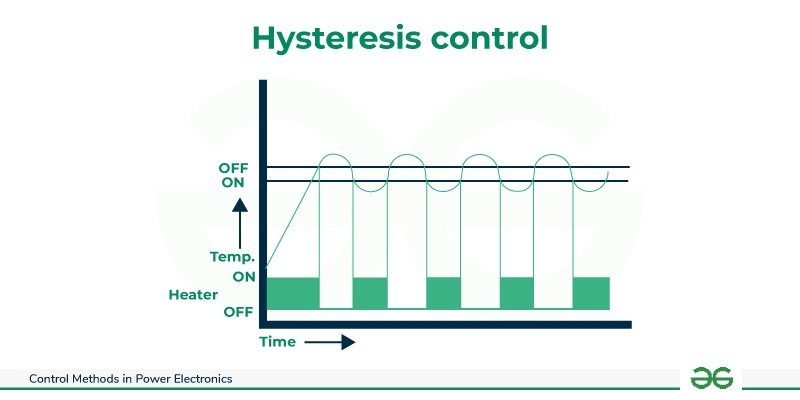
Hysteresis Control
The Hysteresis control introduces a dead band to prevent rapid switching between the states. It is often used in the switching converters and inverters to reduce high-frequency switching noise
Working of Hysteresis Control Mechanism
- Setpoint and Hysteresis Band: The setpoint represents the desired value or threshold for the system. The hysteresis band is the added around the setpoint.
- On State: When the input or output rises above the upper limit of the hysteresis band system switches to “on” state.
- Off State: The system remains in “on” state until the input or output falls below the lower limit of the hysteresis band at which point it switches to “off” state.
- Prevention of Rapid Switching: The Small variations within the hysteresis band do not trigger state changes preventing the rapid and unnecessary switching.
Time Ratio Control
Time Ratio Control known as duty cycle control is a common method employed in the power electronic systems. It involves controlling the on and off times of the power semiconductor devices such as transistors or thyristors. This method is widely used in choppers, inverters and other power converters.
Working Principle
In time ratio control, the duty cycle represents the fraction of the time during which the power semiconductor device is the “on” state compared to the total switching period. The duty cycle is typically expressed as a percentage.
Example
The pulse width modulation (PWM) control scheme the duty cycle determines the width of the pulses generated. By adjusting the duty cycle the average output voltage or current can be controlled.
Applications
- Choppers: In DC-DC converters time ratio control is used to the regulate the output voltage.
- Inverters: In PWM inverters adjusting the duty cycle controls the magnitude of AC output.
Current Limit Control
The Current limit control is a protective mechanism used in the power electronic converters to the prevent excessive current flow through the system. It is crucial for the ensuring the safety and reliability of the power electronic devices.
Working Principle
In current limit control, a predefined threshold is set for the maximum allowable current. If the current surpasses this limit the control system intervenes to limit or reduce the current flow. This is typically achieved by the modulating the duty cycle or adjusting the control signals to power switches.
Applications
- Converters: The Current limit control is essential in the DC-DC converters and AC-DC converters to protect components from the overcurrent conditions.
- Motor Drives: In motor control applications current limit control protects the motor and associated electronics during the abnormal conditions.
Examples
- Voltage Inverter: The PWM is employed in voltage inverters to regulate the output voltage by the adjusting the pulse width.
- Motor Speed Control: The Feedback control is used in the motor control applications to adjust the input power based on the desired speed and actual speed of the motor.
FAQs on Control Methods
Q1. How does PWM contribute to energy efficiency in power electronics?
The PWM allows precise control of the power delivery by adjusting the duty cycle optimizing the energy efficiency in electronic systems.
Q2. What is the role of feedback control in power electronic devices?
The Feedback control ensures that the output of the power electronic devices remains constant by the continuously adjusting the input based on the output conditions.
Q3. Why is hysteresis control important in power converters?
The Hysteresis control reduces rapid switching minimizing the high-frequency noise and improving the overall stability of the power converters.
Share your thoughts in the comments
Please Login to comment...