In Digital System Circuit, an Encoder is a combinational circuit that takes 2n input signal lines and encodes them into n output signal lines. When the enable is true i.e., the corresponding input signal lines display the equivalent binary bit output.
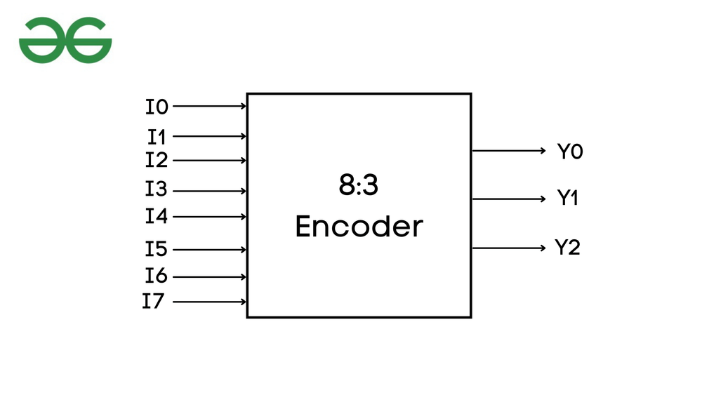
For example, 8:3 Encoder has 8 input lines and 3 output lines, 4:2 Encoder has 4 input lines and 2 output lines, and so on.
An 8:3 Priority Encoder has seven input lines i.e., i0 to i7, and three output lines y2, y1, and y0. In 8:3 Priority Encoder i7 have the highest priority and i0 the lowest.
Truth Table:
| |
Input
|
Output
|
| en |
i7 |
i6 |
i5 |
i4 |
i3 |
i2 |
i1 |
i0 |
y2 |
y1 |
y0 |
| 0 |
x |
x |
x |
x |
x |
x |
x |
x |
z |
z |
z |
| 1 |
0 |
0 |
0 |
0 |
0 |
0 |
0 |
1 |
0 |
0 |
0 |
| 1 |
0 |
0 |
0 |
0 |
0 |
0 |
1 |
x |
0 |
0 |
1 |
| 1 |
0 |
0 |
0 |
0 |
0 |
1 |
x |
x |
0 |
1 |
0 |
| 1 |
0 |
0 |
0 |
0 |
1 |
x |
x |
x |
0 |
1 |
1 |
| 1 |
0 |
0 |
0 |
1 |
x |
x |
x |
x |
1 |
0 |
0 |
| 1 |
0 |
0 |
1 |
x |
x |
x |
x |
x |
1 |
0 |
1 |
| 1 |
0 |
1 |
x |
x |
x |
x |
x |
x |
1 |
1 |
0 |
| 1 |
1 |
x |
x |
x |
x |
x |
x |
x |
1 |
1 |
1 |
Logic Symbol:
Implement Priority Encoder In Verilog Code:
Most of the programming deals with software development and design but Verilog HDL is a hardware description language that is used to design electronics design. Verilog provides designers to design the devices based on different levels of abstraction that include: Gate Level, Data Flow, Switch Level, and Behavioral modeling.
Behavior Modeling:
Behavioral Model which is the highest level of abstraction, Since we are using Behavioral Modeling we shall write the code using if-else to ensure the Priority Encoder input values. By using the if condition the output values are assigned based on the priority.
Design Block: Behavior Modeling
module priorityencoder_83(en,i,y);
  // declare
  input en;
  input [7:0]i;
  // store and declare output values
  output reg [2:0]y;
  always @(en,i)
  begin
    if(en==1)
      begin
        // priority encoder
        // if condition to choose
        // output based on priority.
        if(i[7]==1) y=3'b111;
        else if(i[6]==1) y=3'b110;
        else if(i[5]==1) y=3'b101;
        else if(i[4]==1) y=3'b100;
        else if(i[3]==1) y=3'b011;
        else if(i[2]==1) y=3'b010;
        else if(i[1]==1) y=3'b001;
        else
        y=3'b000;
      end
     // if enable is zero, there is
     // an high impedance value.
    else y=3'bzzz;
  end
endmodule
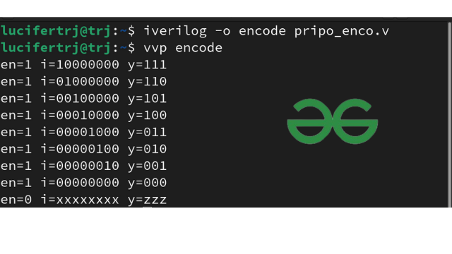
Testbench: Behaviour
A Testbench is a simulation block that is used to provide inputs to the design block. The best way to write Testbench is having is a good insight into the truth table. Once you have the truth table ready provide the input values inside the testbench.
module tb;
  reg [7:0]i;
  reg en;
  wire [2:0]y;

  // instantiate the model: creating
  // instance for block diagram
  priorityenoder_83 dut(en,i,y);
  initial
    begin
      // monitor is used to display the information.
      $monitor("en=%b i=%b y=%b",en,i,y);
      // since en and i are input values,
      // provide values to en and i.
      en=1; i=128;#5
      en=1; i=64;#5
      en=1; i=32;#5
      en=1; i=16;#5
      en=1; i=8;#5
      en=1; i=4;#5
      en=1; i=2;#5
      en=1; i=0;#5
      en=0;i=8'bx;#5
      $finish;
    end
endmodule
Output:
Data Flow Modeling:
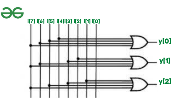
In Data flow modeling we define the output i.e, net by assigning input values i.e., reg using assigned keywords. In order to write Data Flow modeling and gate-level modeling, we require a logic diagram to form connections.
Here is the logic diagram of the 8:3 Priority Encoder
Data Flow Modeling
Design Block: Data Flow
module priorityenoder83_dataflow(en,i,y);
    // declare port list via input and output
    input en;
    input [7:0]i;
    output [2:0]y;

    // check the logic diagram and assign the outputs
    assign y[2]=i[4] | i[5] | i[6] | i[7] &en;
    assign y[1]=i[2] | i[3] | i[6] | i[7] &en;
    assign y[0]=i[1] | i[3] | i[5] | i[7] &en;

endmodule
Testbench: Data Flow
module tb;
  reg en;
  reg [7:0]i;
  wire [2:0]y;

  // instantiate the model: creating
  // instance for block diagram
  priorityenoder83_dataflow dut(en,i,y);
  initial
    begin
      // monitor is used to display the information.
      $monitor("en=%b i=%b y=%b",en,i,y);

      // since en and i are input values,
      // provide values to en and i.
      en=1;i=128;#5
      en=1;i=64;#5
      en=1;i=32;#5
      en=1;i=16;#5
      en=1;i=8;#5
      en=1;i=4;#5
      en=1;i=2;#5
      en=1;i=1;#5
      en=0;i=8'bx;#5
      $finish;
    end
endmodule
Output:
Gate Level Modelling:
In gate-level modeling, we make use of Digital logic gates used in Digital Electronics.
Syntax:
logicgate object(out,in1,in2);
Example:
and a1(out,a,b);
Design Block: Gate-level
module priorityenoder83_gate(en,i,y);
    // declare port list via input and output
    input en;
    input [7:0]i;
    output [2:0]y;

    wire temp1,temp2,temp3; // temp is used to apply
                            // enable for the or gates
    // check the logic diagram and use
    // logic gates to compute outputs
    or o1(temp1,i[4],i[5],i[6],i[7]);
    or o2(temp2,i[2],i[3],i[6],i[7]);
    or o3(temp3,i[1],i[3],i[5],i[7]);

    and a1(y[2],temp1,en);
    and a2(y[1],temp2,en);
    and a3(y[0],temp3,en);

endmodule
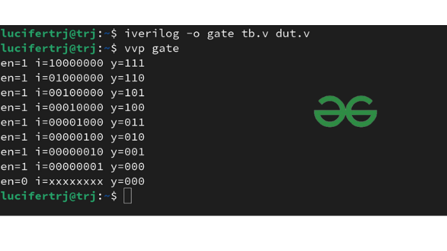
Testbench: Gate-level
module tb;
  reg en;
  reg [7:0]i;
  wire [2:0]y;

  // instantiate the model: creating
  // instance for block diagram
  priorityenoder83_gate dut(en,i,y);
  initial
    begin
      // monitor is used to display
      // the information.
      $monitor("en=%b i=%b y=%b",en,i,y);
      // since en and i are input values,
      // provide values to en and i.
      en=1;i=128;#5
      en=1;i=64;#5
      en=1;i=32;#5
      en=1;i=16;#5
      en=1;i=8;#5
      en=1;i=4;#5
      en=1;i=2;#5
      en=1;i=1;#5
      en=0;i=8'bx;#5
      $finish;
    end
endmodule
Output:
Application of Priority Encoder:
- Robotic vehicles
- Health monitoring systems in Hospitals
Share your thoughts in the comments
Please Login to comment...