The development of relays was started in the period 1809. As a part of the development of the electrochemical telegraph, the electrolytic relay was found by Samuel in the year 1809. From there on, this creation was attested by the researcher Henry in 1835 to make an advanced version of the telegraph and later developed this in the year 1831. While in 1835, Davy totally found the relay, yet the first patent privileges were given by Samuel in the year 1840 for the underlying development of the electric relay. Furthermore, this article gives an unmistakable clarification of understanding what a transfer is, various types of relays, working, and numerous other related ideas.
Relays are the essential security as well as exchanging gadgets in the greater part of the control cycles or gear. Every one of the Relays answer at least one electrical amounts like voltage or flow to such an extent that they open or close the contacts or circuits. A Relays is an exchanging gadget as it attempts to seclude or have an impact on the condition of an electric circuit starting with one state then onto the next.
What is Relay?
Relays are for the most part utilized where it is expected to direct a circuit through an individual insignificant power signal or utilized where various circuits should be managed through a solitary sign. The underlying usage of Relays was in the drawn out length of broadcast circuits like sign repeaters as they empower the wave that is gotten and sends to different circuits. The significant execution of Relays was in phone trades and the underlying variant of PCs.
Reclosing relays are utilized to interface different parts and gadgets inside the framework organization, like synchronizing process, and to reestablish the different gadgets not long after any electrical shortcoming evaporates, and afterward to associate transformers and feeders to line organization. Directing relays are the changes that contacts with the end goal that voltage supports around as on account of tap evolving transformers. Helper contacts are utilized in circuit breakers and other defensive hardware for contact augmentation. Checking relays screen the framework conditions like the heading of force and appropriately produces the caution. These are likewise called directional relays.
The overall sort of a relays utilizes electromagnet to perform opening and shutting of contacts, while in different kinds of approaches like in the strong state sort of transfers they use semiconductor properties for the end goal of controlling without relying upon the mobile parts. Relays those have aligned properties and, at times, different working loops are utilized to defend electric circuit frameworks from over-burden flows. In the ongoing day power systems, these activities are achieved by computerized gadgets where those are called defensive sorts of relays.
Construction of Relay
Construction of Relay
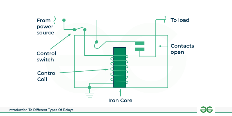
A relay is an electromechanical device comprising of a few key parts:
- Coil: Regularly made of copper wire, the coil is twisted around an iron center. At the point when current moves through the coil, it creates an magnetic field.
- Armature: It is a movable part, frequently a switch or a turned design, associated with a bunch of electrical contacts.
- Contacts: The rely has at least one arrangements of contacts that are normally open (NO) or normally closed (NC) when the relay is in its de-empowered state.
- Spring: The spring gives the power to return the armature to its unique position when the coil is de-empowered.
Operation of Relay
The use of an electromagnet to control the opening or closing of electrical contacts within a relay is necessary for its operation. Transfers are regularly utilized in electrical and electronic circuits to switch high-power loads utilizing a low-power control signal. Here is a bit by bit clarification of how a transfer works:
Coil and Electromagnet
An electromagnet is created by a coil in a relay, typically made of wire wound around a core. A magnetic field is created around the core of the coil as current flows through it.
Contacts that are normally open (NO) and normally closed (NC)
- Electrical contacts can be found in relays in one or more sets. Normally Open (NO) or Normally Closed (NC) are the naming conventions for these contacts. As a default, they are:
- Typically Open (NO) contacts are open (not leading) when the transfer isn’t empowered.
- When the relay is not energized, the normally closed (NC) contacts close and conduct electricity.
Energizing the Coil
At the point when an electric flow is applied to the curl of the hand-off, it makes an attractive field around the loop’s center. The amount of current passing through the coil determines how strong this magnetic field is.
Attraction by Magnetism
The attractive field produced by the loop draws in an armature or an iron center . The relay switches its contacts as a result of this movement of the armature, also known as the core.
Contact Closure (Activation)
The Normally Open (NO) contacts close (conduct) when the armature or core is attracted, completing the relay’s electrical circuit. The NC contacts may open simultaneously, interrupting another part of the circuit.
Contact Opening (Deactivation)
- The magnetic field weakens when the coil’s current is interrupted or reduced below a certain threshold. This makes the armature or center re-visitation of its unique position. Subsequently, the contacts return to their default state:
- Contacts are normally open (NO).
- Contacts are usually closed (NC).
Switching High-Power Loads
Switching high-power loads is accomplished by opening and closing the relay’s controlled contacts. A relay, for instance, can be controlled by a low voltage and current control signal that switches a much higher voltage and current for motors, heaters, and lights.
Different Types of Relays
These relays are developed with electrical, mechanical, and attractive parts, and have working coil and mechanical contacts. Subsequently, when the coil gets enacted by a supply system, these mechanical contacts get opened or closed. The kind of supply can be AC or DC. These electromagnetic relays are additionally classified as
- DC vs AC relays
- Induction type
- Attraction type
- Solid State Relay
- Reed Relay
DC Vs AC relays
Both AC and DC relays work on a similar standard as electromagnetic induction, yet the development is fairly separated and furthermore relies upon the application for which these relays are chosen. DC relays are utilized with a freewheeling diode to de-energize the coil, and the AC relays utilize covered centers to forestall eddy current losses.
The extremely fascinating part of an AC is that for each half cycle, the heading of the current supply changes; in this manner, for each cycle, the coil loses its attraction since the zero current in each half-cycle makes the relay persistently make and break the circuit. Furthermore, some concealed coil electronic circuit is put in the AC relays to give attraction in the zero current position.
Induction Type Relay
These are utilized as protective relays in AC systems alone and are usable with DC systems. The impelling power for contact development is created by a moving guide that might be a circle or a cup, through the connection of electromagnetic transitions because of fault currents.
These are of a few sorts like a shaded pole, watt-hour, and induction cup structures and are for the most part utilized as directional relays in power-framework security and furthermore for fast exchanging activity applications. In view of the design, induction relays are delegated:
Shaded Poles – Organized pole is by and large enacted by the progression of current in a solitary loop which is injured on an attractive design that has an air gap. The air gap dangers created by the changing current are separated as two transition uproot by a concealed shaft and in time-space. This shaded ring is developed with copper material that encompasses each segment of the pole.

Induction-type-Relay
Double Winding also Called as Watt/hr Meter – This kind of relay is incorporated with an E and U-formed electromagnet having a circle allowed to in the middle of between the electromagnets. The stage shift which in the middle of between the motions created by the electromagnet is accomplished by the created transition of the two electromagnets which have different obstruction inductance values for both the circuit systems.
Induction Cup – This depends on the hypothesis of electromagnetic enrollment thus named as acceptance cup relays. The gadget comprises of one or the other at least two electromagnets where those are actuated by the coil present in the relay. The coil that encompasses the electromagnet makes the revolving magnetic field, Because of this rotating attractive field, there will be an enrollment of current in the cup thus the cup will turn. The ongoing turn course is like that of the cup pivot heading.
Attraction Type Relay
These relays can work with both AC and DC supply and draw in a metal bar or a piece of metal when power is provided to the coil. This can be drained being drawn towards the solenoid or an armature being drawn to the posts of an electromagnet as displayed in the figure. These relay have no time delays so these are utilized for the prompt activity. There exist more varieties in the kind of electromagnetic relay and those are:
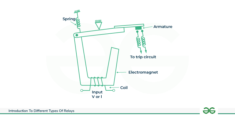
Attraction type Relay
Balanced ream :Here, two quantifiable amounts are connected because of the created electromagnetic tension shifts two fold to the quantity of ampere-turns. The extent of useful current for this sort of transfers is extremely insignificant.
Pivoted armature : Here the relay’s awareness can be improved for DC usefulness by embedding the long-lasting magnet. This is likewise named as energized development relay.
Solid State Relay
Solid State utilizes solid-state parts to play out the exchanging activity without moving any parts. Since the control energy required is a lot of lower contrasted with the result power with be constrained by this relay that outcomes in the power gain higher when contrasted with the electromagnetic relays. These are of various types: transformer-coupled SSR, photograph coupled SSR, etc.
The above figure shows a photograph coupled SSR where the control signal is applied by Drove and it is identified by a photosensitive semiconductor device. The result from this photodetector is utilized to set off the door of TRIAC or SCR that switches the load.

Solid-State-Relay
In the transformer-coupled sort of strong state relay, a negligible measure of DC current is given to the essential twisting of the transformer utilizing a converter of type DC to AC. The provided current is then changed to AC type and moved forward to make the SSR to work alongside the setting off circuit. How much segregation between the result and info areas depends on the transformer plan.
While in the situation of photograph coupled strong state gadget, a photosensitive SC gadget is utilized for the changing usefulness to happen. A directed sign is given to the Drove and this makes the photosensitive part move into conduction mode through the discovery of light that is transmitted from the Drove. The seclusion that is produced from the SSR is similarly more when contrasted and that of the transformer-coupled type due to photodetection theory.
For the most part, SSR’s have faster exchanging speeds than that of electromechanical kind of relays. Additionally as there are no portable parts, its life period is more and they produce insignificant commotion as well.
Reed Relay
Reed Relays comprise of a couple of attractive strips (likewise called reed) that is fixed inside a glass tube. This reed goes about as both an armature and a contact edge. The attractive field applied to the coil is folded over this cylinder that makes these reeds move so that exchanging activity is performed.
In view of aspects, relays are separated as microminiature, subminiature and smaller than normal relays. Likewise, in view of the development, these relays are named airtight, fixed, and open type relays.
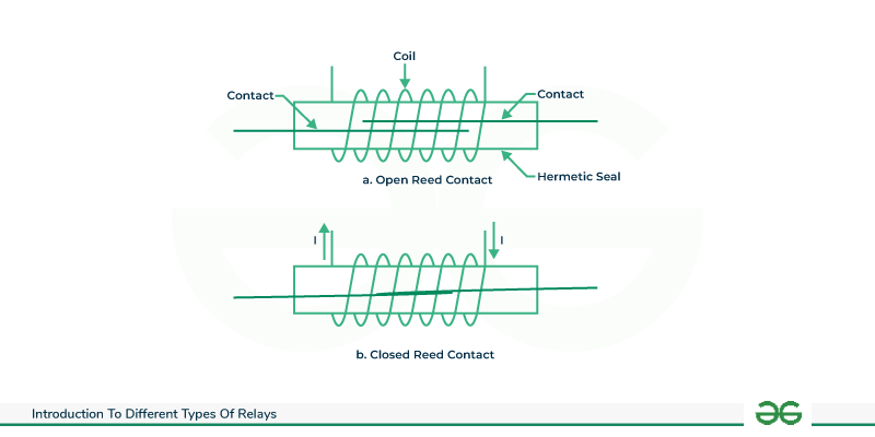
Reed-Relay
Relays are additionally accessible with various pin designs like 3 pins, 4 pins, and 5 pin transfers. The manners by which these relays are worked is displayed in the below figure. Exchanging contacts can be SPST, SPDT, DPST, and DPDT types. A portion of the relays are regularly open (NO) type and the other is ordinarily shut (NC) types.
Polarized Relay and Non-Polarized Relay
On moving further we will explain the terms polarized and non polarized relay:
Polarized Relay
The Polarized Relay utilizes a super durable magnet with an electromagnet. The permanent magnet gives a fixed situation to the armature. The electromagnetic coil changes the place of the armature about a proper turn. The armature position relies upon the extremity of the control input.

Polarized-Relay
An Polarized Relay has a distinct positive and negative terminal for the coil. It requires right extremity for appropriate activity. It frequently incorporates a diode for protection against reverse voltage.
Non-Polarized Relay
The Non-Polarized Relay doesn’t utilize permanent magnets and their coil can be empowered in the two ways without affecting its operation. Some Relay having back EMF diodes has polarity since the diode will sidestep the coil assuming that the association is reversed.

Non-Polarized Relay
A non-polarized relay doesn’t have explicit coil terminals. It works no matter what the polarity of the applied voltage.
Functions of Relay
Relays serve different capabilities, including:
- Switching Function: The essential capability is to go about as a switch that opens or shuts an electrical circuit. It permits a low-power sign or circuit to control the activity of a more powerful circuit.
- Signal Amplification: Transfers can enhance weak electrical signs. A little control signal, like a low-voltage or low-current info, have some control over a transfer that switches a lot bigger voltage or current in the result circuit.
- Controller: Transfers empower controller of electrical gadgets. By utilizing a control signal from a good ways, transfers have some control over gadgets without the requirement for direct actual contact.
- Protection: Transfers are frequently used to give insurance to electrical frameworks. Relays, for instance, can quickly disconnect a circuit in power distribution systems in the event of overcurrent, overvoltage, or other abnormal conditions to prevent equipment damage.
- Time Delay: A time delay between the activation of the control signal and the actual switching of the relay contacts is made possible by time delay relays, which introduce a delay into the switching process. Here timing is basic.
- Sequence Control: When multiple processes or devices need to be controlled in order, sequence control systems make use of relays. Each transfer in the grouping is enacted in a particular request to accomplish the ideal outcome.
- Interlocking: Interlocking systems made possible by relays prevent operations from going against one another. For instance, in engine control circuits, transfers can guarantee that specific tasks can’t happen at the same time, causing harm or risky circumstances.
- Isolation of Signals: Between the load circuit and the control circuit, relays provide electrical isolation. In environments where electrical noise must be minimized or where the control and load circuits operate at different voltage levels, this is crucial.
Instructions to Test Relay
Relays need to be tested to make sure they work right and are reliable in electrical and electronic systems. Here are a few normal techniques and methodology utilized for testing relays:
- Visual Examination: Visually inspect the relay to look for signs of overheating, loose connections, or physical damage. Examine the relay housing, terminals, and wiring.
- Progression Test: Conduct a continuity check on the relay contacts with a multimeter. In both energized and de-energized states, check for continuity (low resistance) across the Normally Open (NO) and Normally Closed (NC) contacts.
- Measuring Resistance: Using a multimeter, measure the resistance of the relay coil. Contrast the deliberate opposition and the predefined esteem in the hand-off’s datasheet. A huge deviation from the normal opposition might demonstrate a shortcoming.
- Testing of Functions: Verify that the relay operates as intended by applying the rated voltage to the coil. Keep an eye on the armature’s movement and the state of the contacts (open or closed). Guarantee that the relay answers accurately to the control signal.
- Protection Obstruction Test: Conduct an insulation resistance test to determine whether the relay’s insulation has failed. While taking measurements of the insulation resistance, apply a high voltage across the coil and relay contacts. The resistance to insulation ought to be within acceptable ranges.
- Test of Dielectric Strength: Perform a high-potential or dielectric strength test to confirm that the relay can withstand high voltages without failing. This test ensures that there is sufficient insulation between the contacts and the coil of the relay.
- Measurement of Response Time: Applying and removing the control signal allows you to measure the response time of the relay. In applications where precise timing is required, response time is crucial. Compare the relay’s specifications to the measured response time.
- Measuring Contact Resistance: Measure the opposition across the shut contacts (shut condition) of the transfer utilizing a low-obstruction ohmmeter. Extreme contact opposition can prompt overheating and ought to be tended to.
- Protection Relay Secondary Injection Test: Perform a secondary injection test on power system protection relays. To simulate fault conditions, a test voltage and a test current must be injected into the voltage inputs of the relay.
- Imaging with heat: Utilize a warm imaging camera to review the push back any strange intensity age during activity. Overheating can demonstrate an expected issue.
Advantages of Different Types of Relays
Various types of relays fill different needs in electronic and electrical frameworks. Here are a few benefits related with normal sorts of transfers:
Electromagnetic Relays
- Versatility: Electromagnetic relays can switch AC or DC loads and are reasonable for a great many applications.
- Cost-Effective: Electromagnetic relays are many times more savvy than strong state transfers.
- High Power Handling: They can deal with moderately high power loads, making them appropriate for modern applications.
Induction Type Relay
- Fast operation: The construction of induction type relay is robust also it has fast operation abilities which makes it fast and easy to operate .
- Cost effective : The induction type relay are lower in cost and also can stand with higher voltages, which makes it reliable and accurate .
- Versatile : Induction type relay can work in other abnormal situations also which is done with the help of the secondary winding of the relay.
Solid-State Relays (SSR)
- Fast Switching Speed: SSRs have fast exchanging times, giving exact control in applications that require speedy reaction times.
- Silent Operation: Strong state relays work quietly, making them reasonable for clamor touchy conditions.
- Long Life: Since SSRs have no moving parts, they are more solid and have a more drawn out life expectancy contrasted with electromagnetic relays.
Reed Relays
- Compact Size: Reed relays are reduced and lightweight, making them appropriate for applications with restricted space.
- Low Power Utilization: Reed relays for the most part have lower power utilization contrasted with different kinds.
- High Reliability: With no mechanical parts to break down, reed relays offer high dependability and a more drawn out functional life.
Disadvantages of Different Types of Relays
Electromagnetic Relays
- Slower Switching Speed: Contrasted with strong state relays, electromagnetic relays by and large have more slow exchanging speeds.
- Mechanical Wear: Electromagnetic relays have moving parts, and over the long run, mechanical mileage can happen, and have a more limited life expectancy.
Induction Type Relay
- Maintenance : Induction type relay requires proper maintenance and testing of the relay within time .
- High requirement : In this type of relay, the high burdened current and potential transformers are required to operate .
Solid-State Relays (SSR)
- Heat Dispersal: SSRs create heat during activity, and appropriate intensity scattering is essential. In high-power applications, extra cooling measures might be important.
- Voltage and Current Ratings: SSRs might have restrictions on voltage and current appraisals contrasted with electromagnetic relays, which can affect their utilization in high-power applications.
Reed Relays
- Limited Switching Speed: While reed relays are known for their steady quality, they might have limits on exchanging speed, making them less reasonable for fast applications.
- Susceptibility to Magnetic Fields: Outer magnetic fields can influence the activity of reed relays, requiring cautious thought of the establishment climate.
Applications of Different Types of Relays
- Motor Control: Relays are necessary in engine control applications, starting the beginning or stop works and giving security against over-burdens and blames. They control the bearing of engine pivot in forward or switch activities.
- Power Systems and Distribution: Security relays are utilized in power systems to screen voltage, current, and recurrence. They act to separate defective gear or circuits, forestalling harm and guaranteeing framework security. Over-burden relays safeguard engines from unreasonable flows and overheating in power conveyance systems.
- Industrial Automation: Relays are broadly utilized in modern computerization frameworks to control and switch different cycles, apparatus, and hardware. They play a vital role in controlling transport lines, engine starters, siphons, and other modern gadgets.
- Automotive Systems: In automobiles, relays are utilized for different capabilities, including controlling headlights, windshield wipers, cooling frameworks, and starter engines. They assist oversee high-current gadgets with lower current switches.
- Telecommunications: Relays assume a part in signal exchanging and steering inside media communications frameworks. They are utilized in phone trades and correspondence organizations to lay out associations between various lines.
- Home Computerization: Relays are utilized in brilliant home systems to control lights, and other electronic gadgets. They give the point of interaction between low-voltage shrewd home regulators and higher-voltage electrical gadgets.
- Electronic Devices: Relays are utilized in electronic gadgets like PCs and sound enhancers to change capacity to different parts. They empower the segregation of circuits and the control of various pieces of a system.
- HVAC Systems: Warming, ventilation, and cooling (air conditioning) systems use relays to control parts like blowers, fans, and warming components. Time postpone relays are utilized for sequencing tasks in HVAC systems.
Conclusion
In conclusion, relays plays a vital role in electrical and electronics systems by giving a method for controlling high-power circuits with low-power signals. Their development, grouping, and activity fluctuate in light of explicit applications and requirements. The decision among polarized and non-polarized relays relies upon the application’s requirements. Ordinary testing and upkeep ensure the steady quality of relays in different modern and private settings. The combination of solid- state relays and keeps on upgrading the productivity and usefulness of these fundamental parts in the domain of electrical control and mechanization.
As the relays ensures the security of the circuit to not let any harm to happen. Each relays includes three urgent parts and those are determined, contrasting, and controlling parts. The determined part knows the variety in the genuine estimation and the contrasting part assesses the genuine sum and that of a prechosen transfer. What’s more, the controlling part handles fast variety in the deliberate limit like the end of the ongoing practical circuit.
FAQs on Types of Relays
1. What is mean by relay?
A relay is an electromechanical or strong state gadget that capabilities as a switch, permitting a low-power sign to control a powerful circuit.
2. Where are reed relays usually utilized?
Reed relay are many times utilized in applications where conservative size, high dependability, and low power utilization are basic, like in media communications and programmed test hardware.
3. What are the upsides of solid state relays (SSR) over electromagnetic relays?
Solid state relay offer benefits, for example, quicker exchanging speeds, longer life expectancy because of no moving parts, and quiet activity. They are likewise reasonable for high-recurrence applications.
4. How does an electromagnetic relay work?
An electromagnetic relay utilizes an electromagnet to work a switch precisely. At the point when the curl is empowered, it creates an attractive field that draws in a versatile armature, shutting or opening the contacts.
5. What are the fundamental types of transfers?
The principal kinds of relay incorporate electromagnetic relay, strong state relay (SSR), reed relay, over-burden relay, time postpone relay, and warm relay.
Share your thoughts in the comments
Please Login to comment...