Quarter Wave Transformer
Last Updated :
27 Feb, 2024
To match impedances, a quarter-wave transformer is a basic tool in electrical engineering and RF circuit design. Basically, it’s a section of transmission line that helps guarantee effective power transfer from a source to a load. It has a set length. In radio frequency (RF) and microwave engineering, a quarter-wave transformer is an essential tool for matching the impedance of a transmission line to that of a load. This reduces signal reflections and guarantees effective power transfer .
What is Quarter Wave Transformer?
A quarter wave transformer, sometimes referred to as a quarter-wave impedance transformer, is a matching network or transmission line used in microwave and radio frequency (RF) engineering. Its main function is to match the impedance of a transmission line segment to another, facilitating effective power transfer between various radio frequency circuit components.
The Quarter Wave Transformer’s basic idea is derived from the connection between a transmission line’s physical length and electrical wavelength (λ). A transmission line experiences a 90-degree phase change in impedance when it is a quarter wavelength long at a specific frequency. This characteristic is utilized to convert the impedance between two values.

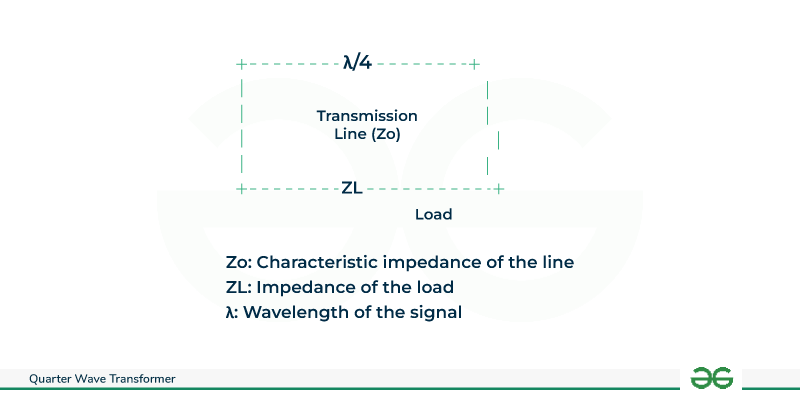
Quarter-Wave-Transformer
Key Terminologies of Quarter Wave Transformer
- Impedance characteristic (Zo): This is the transmission line’s intrinsic impedance, expressed in ohms (Ω), that the transformer uses. For a particular power level, it calculates the voltage and current present. Ideally, for maximum power transfer and least amount of reflections, the load impedance (ZL) should match Zo.
- ZL, or load impedance: This is the circuit’s or device’s impedance, which is also expressed in ohms, when connected to the transformer’s output. Signal reflections from mismatched ZL and Zo lower efficiency and may even break components. In order to achieve impedance matching, quarter-wave transformers “transform” ZL such that it appears as Zo at the input.
- λ/4, or quarter-wavelength: This is the critical length where the transformer functions well. By guaranteeing a particular phase shift in the line, impedance matching can occur when the reflected wave cancels out the original wave at the input.
- Coefficient of Reflection (Γ): The portion of the signal that is reflected back as a result of an impedance mismatch is indicated by this dimensionless parameter. Perfect matching, or no reflection, is represented by a value of 0, whereas numbers nearer 1 indicate larger levels of reflection.
Construction of Quarter Wave Transformer
All that a quarter-wave transformer is is a transmission line adjusted to a certain length and operating frequency. Although coaxial cable is typically used to construct it, alternative transmission line types, such as microstrip or stripeline, can also be used.
- Establish the Operating Frequency : Determine your system’s operating frequency.
- Determine the Wavelength: Utilize the following formula: ⁰ = ⁰ ⁰λ= f c , where f is the frequency, ⿰λ is the wavelength, and c is the speed of light (about 3 × 10^8 meters per second).
- Quarter-wavelength calculation: To find the quarter-wavelength (㿰 / 4λ/4), divide the wavelength by 4.
- Choose the Type of Transmission Line: Select the kind of transmission line that you want to use, such as coaxial cable.
- Determine the Impedance Characteristic: Determine the transmission line’s characteristic impedance (0 Z 0). This is a basic transmission line specification that the manufacturer would often specify.
- Determine the Physical Length: Determine the quarter-wave transformer’s physical length by applying the formula V = V 4 L = 4 λ.
- Build the Transformer: Cut a transmission line segment to the specified length. This part will serve as the transformer for quarter waves.
- Link to the System: Attach the source or load to one end of the quarter-wave transformer and the desired matching transmission line to the other end.
.png)
Construction of Quarter-Wave-Transformer
Working of Quarter Wave Transformer
- Impedance Transformation: The quarter-wavelength electrical length of the quarter-wave transformer causes a 90-degree phase shift in signals as they pass through it. An alteration in impedance is the outcome of this phase transition.
- Reduce Reflections: At the junction of the two transmission lines, the Quarter-Wave Transformer is made to reduce reflections. The transformer maximizes power transfer and minimizes signal reflections by establishing impedance matching.
- Effective Matching: The transformer matches the source’s and the load’s impedances in an effective manner. To avoid signal loss and guarantee effective power transfer, this is essential in RF and microwave systems.
- Consider a signal that is moving toward a load that has a different impedance (ZL) from a source that has typical impedance (Zo). Reflections from this mismatch lower efficiency and skew the signal.
- Like a magical bridge, the quarter-wave transformer functions. Its length and Zo are carefully selected so that the reflected wave experiences another impedance shift at the transformer’s input. By essentially canceling out the reflected wave, the second modification stops the wave from returning to the source.
- Consequently, at the transformer’s input, the load “sees” an impedance that is the dual of its own. In doing so, a matched situation is produced, which maximizes power transfer and reduces signal distortion.
Parameters of Quarter-Wave Impedance Transformer
- Length: The transformer is a transmission line segment whose length is precisely equal to a quarter of the signal’s wavelength (λ/4). This guarantees certain phase changes in the line.
- Impedance matching: Reflections arise when the transmission line’s characteristic impedance (Zo) and load impedance (ZL) disagree, leading to signal distortion and loss. In its capacity as an impedance transformer, the quarter-wave transformer reflects the signal back with a 180° phase shift. In order to achieve impedance matching and reduce reflections, this essentially “cancels out” the original reflected wave at the input.
- Duality: The output impedance of the transformer is equal to its termination impedance times two. This indicates that the transformer offers a lower impedance at its input if the load has a higher impedance than the line.
Quarter-Wave-Transformer Parameters
Remember our formula for the input impedance of a transmission line of length L that is connected to a load with an impedance of ZA and has characteristic impedance Z0:
Formula
Zin (-1) = Zo
ZA+ jZo tan(BL) Zo+jZA tan(BL)
When the line is one-fourth of the wavelength in length, an intriguing phenomenon occurs. The above equation is significant because it shows how the impedance of the load (ZA) can be changed using a transmission line with a quarter-wavelength. Through an example, the usefulness of this procedure is demonstrated.
Example
Match a load using a quarter-wave transformer to have an impedance of ZA = 100 Ohms to 50 Ohms.

Quarter-Wave-Transformer Example
The solution is to find Z0, our quarter-wavelength transmission line’s characteristic impedance, so that the load of 100 ohms is matched to 50 ohms. Using the equation above, the issue becomes straightforward:
Zin (L 50 = ==z3 100) 금 ZA =・→20=√ (50) (100) 70.712
Quarter-Wave Transformer in Antenna Systems
A quarter-wave transformer is essential for impedance matching in antenna systems .In antenna systems, a particular kind of transmission line section called a quarter-wave transformer is used to match the impedance of an antenna to that of a transmission line. Impedance matching is essential for effective power transfer, reducing signal reflections, and maximizing antenna system performance.
- Impedance Matching: When the impedance at the antenna terminals matches the characteristic impedance of the transmission line or feedline, antenna performance is at its best.
- Characteristics of the Transmission Line: Usually 50 or 75 ohms, the characteristic impedance (0 Z 0 ) of the transmission line that connects the antenna to the transmitter or receiver.

Antenna System
Functions of Quarter Wave Transformer
A quarter-wave transformer, as you were previously taught, is a section of transmission line whose length is equivalent to one-quarter of the signal’s wavelength (λ/4) at the operating frequency.
Its main function in antenna systems is to adjust the feedline’s impedance, which is usually 50 ohms, to match the antenna’s impedance at the feed point. By reducing RF signal reflections back towards the transmitter, this impedance matching maximizes power transfer and boosts antenna efficiency.
Advantages of Quarter-Wave Transformers
- It is possible to match any load impedance to a transmission line by using a quarter wave transformer.
- Designers and engineers favor it because of its affordability, simplicity, and efficacy.
- It is important to recognize its limitations, though, as more extensive uses may call for different matching strategies or suitable design approaches.
- Their efficiency, portability, and ease of use are their strongest points .
- The particular application, the intended performance level, and the frequency range all influence the choice of matching technique
Disadvantages of Quarter-Wave Transformers
- When the load impedance is real-valued is impedance matching feasible.
- Particularly at low frequencies, quarter-wave transformers can have a significant physical footprint.
- The transformer will be unable to produce a perfect match if the load impedance contains a reactive component, either inductive or capacitance.
- The quarter-wavelength of the signal is the only frequency at which a quarter-wave transformer operates efficiently.
Applications of Quarter Wave Transformer
- One quarter wavelength is conveniently short enough to incorporate the component within many products at radio frequencies of upper VHF or higher up to microwave frequencies, but not so small that it cannot be manufactured using standard engineering tolerances. The device is most frequently encountered at these frequencies. It is particularly helpful when converting a capacitor into an inductor because designers favor the latter.
- Another use is when DC power must be supplied into a transmission line in order to power an active component that is linked to the line, such a varactor diode or switching transistor, for example. An perfect DC voltage source offers a short circuit since it has zero impedance.
Conclusion
In conclusion, .efficiency, portability, and ease of use are the strongest points. It is necessary to give careful thought to their limitations with complex loads, restricted bandwidth, and frequency dependence. The particular application, the intended performance level, and the frequency range all influence the choice of matching technique. In antenna systems, the quarter-wave transformer is still a useful instrument, especially for single-frequency or narrow-band applications. Designers and engineers favor it because of its affordability, simplicity, and efficacy. It is important to recognize its limitations, though, as more extensive uses may call for different matching strategies or suitable design approaches.
FAQs on Quarter Wave Transformer
1 . A quarter-wave transformer: what is it?
To change the impedance of one portion of a transmission line to another, a matching network or transmission line is called a quarter-wave transformer. It works on the basis of the idea that a quarter-wavelength transmission line at a certain frequency causes a 90-degree phase shift, which makes it easier for various components in a radio frequency circuit to match impedance.
2 . How does it operate / works ?
The secret is the specific length of the transformer, which is equal to λ/4 at the operating frequency and introduces a wavelength-dependent phase shift. Effective power transfer to the load is made possible by this phase shift, which eliminates reflections brought on by impedance mismatch. See it as akin to flipping a wave that has been reflected back into phase with the original wave, enabling them to “cooperate” rather than collide.
3 . Where does a quarter-wave transformer is used ?
In response, transmission lines, RF/microwave circuits, and antenna systems frequently employ quarter-wave transformers. They are frequently used to minimize signal reflections and maximize power transfer by matching the impedance of antennas to that of transmission lines. Additionally, they are employed in the design of impedance matching networks, baluns, and other RF system components.
4 . Is there any other options?
Yes, depending on the particular requirements, a number of alternative approaches can handle impedance matching:
- Double-stub tuners are more complicated, but they work well to balance reactive loads.
- Baluns: Convert signals from unbalanced (single wire) to balanced (two wires) or the other way around.
- Transformers for transformers: provide wider bandwidth matching than transformers operating at quarter wave.
Share your thoughts in the comments
Please Login to comment...