In this article, we will study the theory of transformer on load and no load operation. A transformer is a static electrical machine used to increase or decrease the value of voltage and current in an electrical circuit. The transformer operates on the principle of electromagnetic induction and mutual inductance. A transformer typically consists of two copper winding and a magnetic core. The windings are named as primary winding and secondary winding. The input supply is connected to the primary winding and the output electrical supply is taken from the secondary winding. Hence, the secondary winding is one to which the electrical load is connected.
Let us understand the operation of a transformer on load and no-load conditions.
A transformer is said to be operated in no-load condition if no electrical load is connected across its secondary winding terminals. In other words, when the secondary winding of a transformer remains open-circuited and no current flows through it, then the transformer is said to be in no-load condition.
When a transformer operates in no-load condition, no current flows in the secondary winding, but a small current called no-load current (I0) which is around 2% to 10% of the rated current flows in the primary winding.
This no-load current I0 magnetizes the core of the transformer and results in some core losses (i.e., iron losses and copper losses).
The following figure depicts the circuit diagram of an electrical transformer in no-load condition.
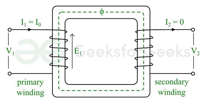
Transformer on No-Load Condition
In this circuit, we can see that there is an input voltage of V1 volts is applied to the primary which forces a no-load current of I0 ampere through it. The secondary winding is open-circuited, hence the secondary I2 is equal to zero amperes.
As we discussed that when a transformer is operated in no-load condition, it draws only a small current called no-load current from the input power supply. This no-load current has two components namely,
- Magnetizing component
- Power component
The magnetizing component is also called the reactive component and it is responsible for setting up the magnetic flux in the core. This component of the no-load current lags the supply voltage V1 by an angle of 90°, as it is due to the inductive effect. This component is usually denoted by Im.
The power component is also called the active component and it is responsible for supplying core losses i.e., iron and copper losses. The active component remains in-phase with the supply voltage. In other words, the angle between the supply voltage V1 and the active component of the no-load current. This component is designated by the symbol Iw.
Therefore, we can express the no-load current of the transformer as the phasor sum of the magnetizing component and the power component i.e.,
[Tex]I_0=I_m+I_w
[/Tex]
Operation of Transformer on No-Load
Here is the operation of a transformer in no-load condition:
- Firstly, the input voltage V1 is applied across the primary winding of the transformer. It magnetizes the core of the transformer by setting up a magnetic flux (ϕ) in it.
- This magnetic flux induces EMFs in the primary and secondary windings due to electromagnetic induction. These induced EMFs lag the applied voltage by an angle of 90°. Here, we are neglecting the primary winding copper loss and the secondary winding copper loss is zero because I2 = 0.
- The no-load current I0 lags behind the supply voltage V1 by an angle of ϕ0 which is called the no-load power factor angle.
- It is also important to note that the EMF E1 induced in the primary winding is equal to the supply voltage V1.
- There are also some losses in the primary winding (copper loss) and the core (iron losses) of the transformer which are represented by the active component (Iw) of the no-load current. This component is equivalent to the resistive effect and hence remains in-phase with the supply voltage (V1).
- This is how an electrical transformer operates under no-load conditions.
This complete operation of the transformer on no-load can be illustrated with the help of a phasor diagram which is shown in the following figure.
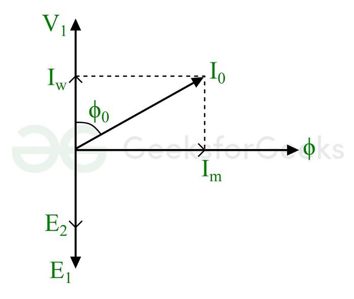
Phasor Diagram of Transformer on No-Load
Phasor Diagram Explanation
- The induced EMF (E1 and E2) are out of phase with respect to the supply voltage (V1) and lags the magnetic flux by 90°.
- The reactive component Im lags the supply voltage V1 by 90°.
- The active component Iw is in-phase with the supply voltage (V1).
- The no-load current I0 lags the supply voltage V1 by an angle φ0 which is the no-load power factor angle of the transformer.
From this phasor diagram, we can derive the important relations of different electrical parameters of the transformer. They are,
(1). The magnitude of no-load current:
[Tex]I_0=\sqrt{I_m^2 + I_w^2}
[/Tex]
(2). The magnetizing component of no-load current:
[Tex]I_m = I_0 sin {\phi_0}
[/Tex]
(3). The active component of no-load current:
[Tex]I_w = I_0 cos \phi_0
[/Tex]
(4). The no-load power factor:
[Tex]cos\phi_0 = \frac{I_w}{I_0}
[/Tex]
(5). The power consumed under no-load:
[Tex]P_0 = V_1 I_0 cos\phi_0
[/Tex]
Hence, this is all about the theory and operation of an electrical transformer in no-load condition.
Let us now study the theory and operation of an electrical transformer under loaded conditions.
A transformer is said to be on load condition if an electrical load is connected to its secondary winding and a current circulates in the secondary winding circuit. The load connected across the secondary winding can be a resistive load or an inductive load or a capacitive load or a combination of the three. Therefore, the magnitude of the secondary winding current also called load current depends on the load impedance and secondary voltage (V2). Also, the phase angle between the secondary voltage and load current depends on the type of the load. For example, if the load is of inductive nature, the load current will lag the secondary voltage.
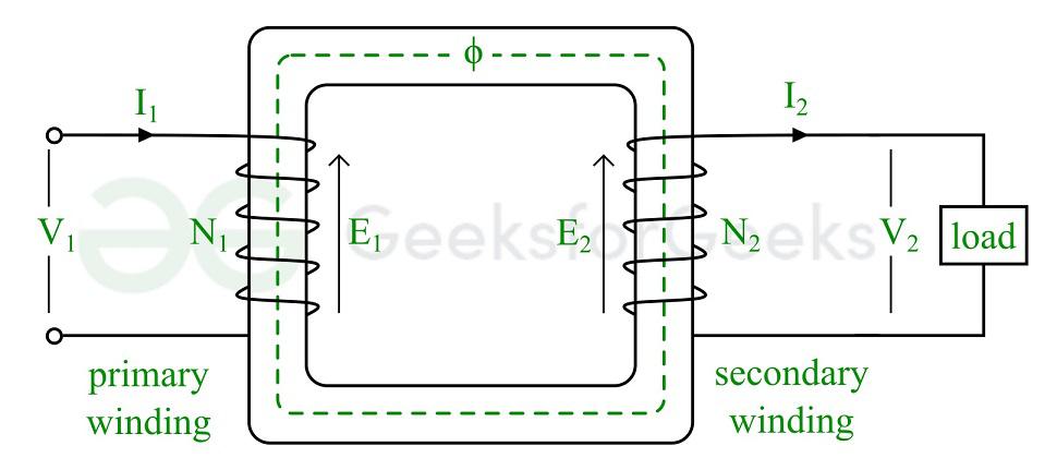
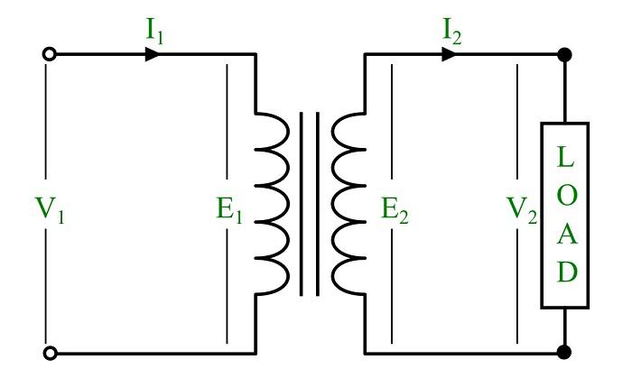
Operation of Transformer on Load
Operation of Transformer on Load
Here is the operation of an electrical transformer operation under loaded condition:
- An electrical input supply voltage V1 is connected across the primary winding. Due to the application of this voltage an electric current I1 will starting flowing in the primary winding and sets up a magnetic flux in the core as shown in the above figure.
- This magnetic flux follows a path through the core and links to the secondary winding.
- An EMF E2 is induced in the secondary winding that developers a voltage V2 across its terminals.
- When a load is connected between the secondary winding terminals, a current will flow in the secondary winding and load circuit which is denoted by I2.
- The secondary winding current also induces a counter magnetic flux that reduces the main flux in the core. But the main flux must be maintained at a constant value for operation of the transformer.
- Thus, an additional current is taken by the primary winding from the supply to cancel out the demagnetizing effect of secondary winding current. This is represented by I’1 which is in-phase with the secondary winding current (I2). Thus, the total current flowing in the primary winding under loaded condition of the transformer is I’1.
Therefore, if N1 and N2 are the primary and secondary winding turns and I’1 and I2 are the primary and secondary currents, then the EMF balance equation of the transformer on load is given by,
[Tex]N_1 I’_1 = N_2 I_2
[/Tex]
Hence, the primary winding current will be,
[Tex]I’_1 = (\frac{N_2}{N_1})I_2 = kI_2
[/Tex]
Also, the total primary winding current (I1) has two main components namely,
- No-load component – to set up main magnetic flux in the core and supply the losses.
- Counter balancing component – to overcome the effect of secondary winding current.
Thus, the total primary winding current of the transformer on load condition is given by,
[Tex]\bold{I_1 = I_0 + I’_1}
[/Tex]
The bold facing letter denotes the phasor sum of current components.
In practice, the transformers mostly have inductive loads. So, let’s assume the load connected across the secondary of the transformer and draw the phasor diagram of it on load condition.
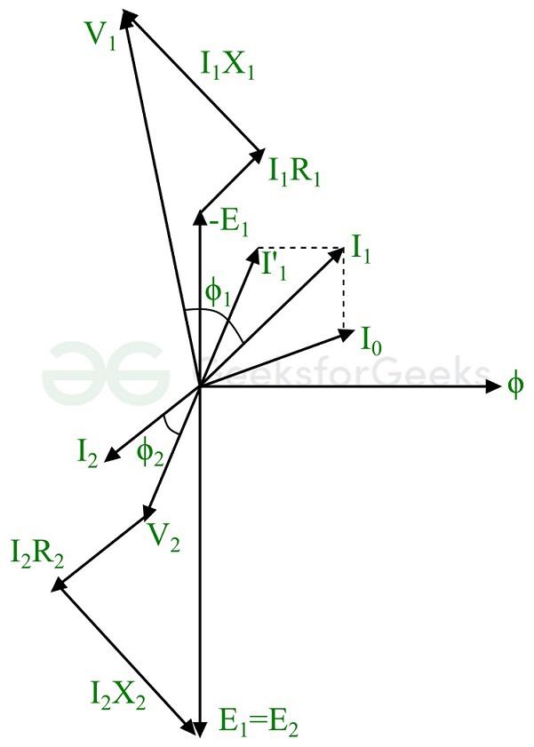
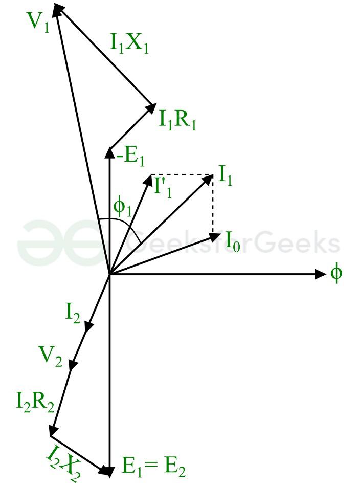
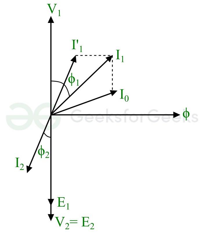
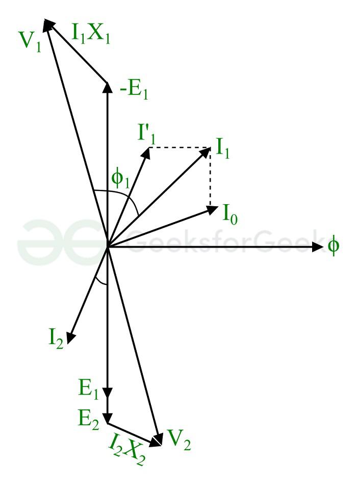
Phasor Diagram of Transformer on Load
Phasor Diagram Explanation
The steps given below are to be followed to draw the phasor diagram of the transformer on load:
Step (1) : Taking main magnetic flux (ϕ) as the reference axis.
Step (2) : This magnetic flux induces EMFs E1 and E2 in primary and secondary windings. Hence, E1 and E2 lags the flux (ϕ) by an angle of 90°.
Step (3) : The applied voltage across the primary winding is utilized in three components namely, to induce emf E1, voltage drop in primary winding resistance I1R1, and voltage drop in primary winding reactance I1X1. Hence, the primary winding voltage V1 is the phasor sum of voltage component corresponding to E1 and the voltage drops in primary winding.
Step (4) : If ϕ1 is the power factor angle of the primary winding, then the current I1 will lag the voltage V1 by ϕ1. It is the phasor sum of no-load current I0 (lags the supply voltage by 90°) and counter balancing current I’1 (in anti-phase with the secondary voltage V2).
Step (5) : The secondary winding EMF E2 is the phasor sum of voltage V2 and the voltage drops in secondary winding resistance and reactance.
Step (6) : The magnitude and phase angle of the load current or secondary current I2 depends on the load connected to the transformer. As in this case, we are assuming an inductive load, hence the load current I2 will lag the voltage V2. If the load is capacitive, the load current will lead the voltage V2.
Thus, when we operate a transformer on load condition, it takes both no-load current and current required to handle the load connected across its secondary winding.
Let us now understand the theory of transformer on load with two other load conditions
- Transformer on load with purely resistive load
- Transformer on load with purely inductive load
- Transformer on load with purely capacitive load
Transformer on Load with Purely Resistive Load
When a purely resistive load is connected across the secondary winding of a transformer, it draws only active current from the transformer. The resistive load creates a phase difference of 0° between the load current and the secondary winding voltage.
The phasor diagram of the transformer on load with purely resistive load is shown in the following figure.
Transformer on Load with Purely Inductive Load
When a purely inductive load is connected across the secondary winding of the transformer. It cause a phase different of exactly 90° between the secondary voltage and load current.
The phasor diagram of a transformer on load with purely inductive load is shown in the following figure. It can be observed that the load current I2 lags the secondary voltage V2 by an angle of 90°.
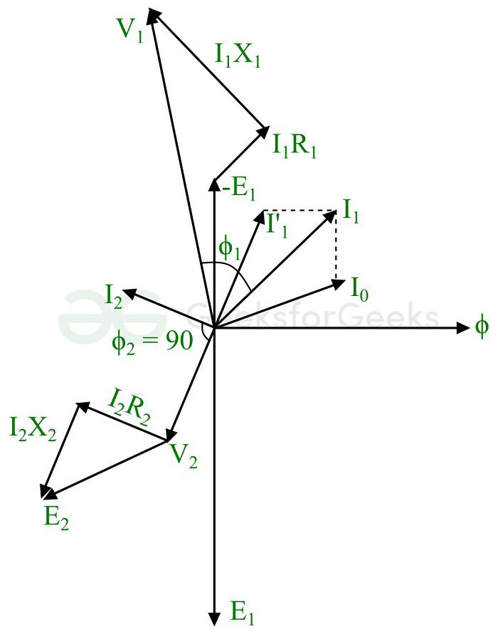
Transformer on Load with Purely Inductive Load
Transformer on Load with Purely Capacitive Load
When a purely capacitive load is attached to the secondary winding of the transformer, it draws a leading current from the secondary winding. This causes a phase difference of 90° between the load current and the secondary voltage. Where, the load current I2 leads the secondary voltage V2 by an angle of 90° as shown in the following phasor diagram.
Transformer on Load with Purely Capacitive Load
Till this section of the article, we have discussed about the operation of a practical transformer on no-load and on-load (with resistive load, inductive load, and capacitive load).
Also, we have analyzed a practical transformer on load with winding resistances and leakage reactances. However, there can be three other possible cases, they are:
- Transformer on Load with No Winding Resistances and Leakage Reactances
- Transformer on Load with Winding Resistances but No Leakage Reactances
- Transformer on Load with Leakage Reactances but No Winding Resistances
Let us understand these three cases of transformer operation on load in detail.
Transformer on Load with No Winding Resistances and Leakage Reactances
When we consider a transformer on load with no winding resistances and leakage reactances, then its electrical circuit will look like as shown in the following figure.
Transformer on Load Having No Winding Resistance and Reactance
In this case, there are no voltage drops due to resistances and leakage reactances of the windings. Thus, the terminal voltages and induced emfs are equal i.e.,
E1 = V1 and E2 = V2
If we consider a practical inductive load connected across the secondary winding, then the load current I2 will lags behind the secondary winding voltage V2 by an angle of ϕ2. Where, ϕ2 is the power factor angle of the load.
In this condition, the primary winding current I1 will supply the following two things:
- It supplies the no-load current I0 to establish magnetic flux in the core and iron losses.
- It cancel out the demagnetising effect of the secondary winding current.
Therefore, the primary winding current is given by,
[Tex]\bold{I_1 = I_0 + I_1′}
[/Tex]
Here, the component I’1 is the counter balance current of the secondary winding current.
If we draw the phasor diagram for this case of the transformer on load, then it will look like as shown below.
Phasor of Transformer having No Winding Resistance and Leakage Reactance
In this phasor diagram, the secondary winding voltage V2 is equal to the secondary winding emf E2 and they are in-phase. While, the primary winding voltage V1 is equal to the primary winding emf E1 but they are out of phase with each other. The primary winding current is the phasor sum of I0 and I’1.
Transformer on Load with Winding Resistances but No Leakage Reactances
The circuit diagram of a transformer on load having winding resistances but no leakage reactances is shown below.
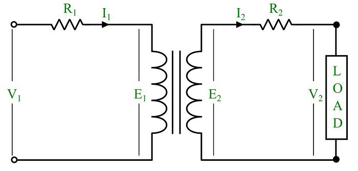
Transformer on Load with Winding Resistance but No Leakage Reactance
In this circuit diagram, the resistors R1 and R2 represent the primary and secondary winding resistances. A practical inductive load is connected across the secondary winding terminals.
When the input voltage V1 is connected to the primary winding, there will be a voltage drop in the primary winding resistance R1 and the secondary winding resistance R2.
Therefore, we get the following equations of the voltages,
[Tex]V_1 = E_1 + I_1 R_1
[/Tex]
And
[Tex]E_2 = V_2 + I_2 R_2
[/Tex]
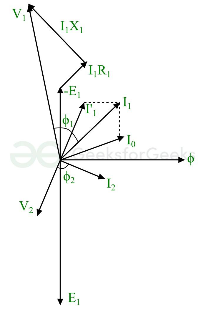
The phasor diagram for this case of transformer on load is depicted in the following figure.
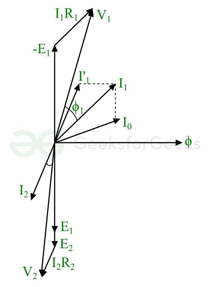
Phasor of Transformer having Winding Resistance but No Leakage Reactance
Transformer on Load with Leakage Reactances but No Winding Resistances
The circuit diagram of a transformer on load having leakage reactances only and not having the winding resistances is shown in the figure.
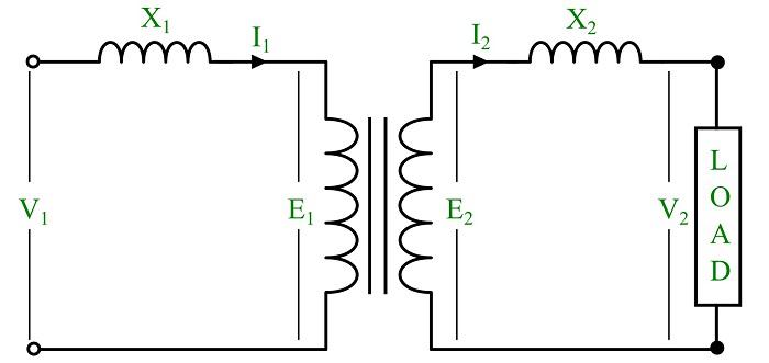
Transformer on Load Having Leakage Reactance but No Winding Resistance
Here, X1 and X2 represents the leakage reactances of the primary and secondary windings respectively.
The voltage equations are given by,
[Tex]V_1 = E_1 + I_1 X_1
[/Tex]
And
[Tex]E_2 = V_2 + I_2 X_2
[/Tex]
The phasor diagram for this case of transformer on load is depicted below. Where, we have considered a practical inductive load.
Phasor Diagram of Transformer on Load Having Leakage Reactance but No Winding Resistance
Conclusion
In conclusion, a transformer is a device used to change the levels of voltage and current in an electric circuit. A transformer when operated with open-circuited secondary winding, it is said to be in no-load operation and when it is operated with attaching a load across its secondary, it is said to be in on-load operation.
In this detailed article on “Theory of Transformer on Load and No-Load Operation”, we have discussed the operation of a transformer under both conditions and explained its behavior using the phasor diagrams.
FAQs on Transformer on Load and No Load Operation
What is main difference between no load transformer and on load transformer?
The most significant difference between a no-load transformer and on-load transformer is that a no-load transformer has a open-circuited secondary winding where no electrical load is connected across its terminals, whereas an on-load transformer has a close-circuited secondary winding. In the case of a no-load transformer, the secondary winding current is always equal to 0 A, but an on-load transformer has certain secondary winding current whose magnitude depends on the load connected across it.
What happen if a current transformer is operated on no-load?
When a current transformer (a type of instrument transformer used in electrical measurement) is operated under no-load condition i.e., open circuited secondary winding, a very large voltage is developed between its secondary winding terminals. Due to high voltage, air between the terminals gets ionized and causes an electric spark of very high intensity that can lead to an electrical accident.
What happens when a transformer is loaded by a short circuit?
When a transformer is loaded by a short-circuit, the secondary winding current becomes too high that will destroy the insulation between the winding and core. This results in burning of the secondary winding.
Share your thoughts in the comments
Please Login to comment...