In this article, we will discuss what is A current Transformer?, Construction of the Current Transformer, Its Working, Phasor Diagram, Errors in the current Transformer, and Its Types, and At last we will conclude this article With its advantages, disadvantages, Application, and FAQs.
To measure high AC current, using an ammeter directly is impractical and potentially hazardous due to the elevated currents involved. Instead of employing an ammeter directly, a current transformer is utilized. A current transformer falls under the category of Instrument Transformers. With the assistance of a current transformer, the measurement of high AC current becomes feasible and safe. The primary function of a current transformer is to step down the high AC current, enabling its safe transmission to measuring instruments, relays, or other monitoring devices. It operates on the same principle as a normal transformer, a concept that will be further discussed in the working part.
The principle of the current transformer is the same as that of a normal transformer; it follows the law of Electromagnetic Induction. (Electromagnetic Induction: a varying magnetic field induces an electromotive force (EMF) or voltage in a conductor).

Current Trasnformer
The figures presented illustrate the construction of the current transformer, featuring a design similar to a typical transformer with two windings: Primary and Secondary Similar to a standard transformer, the input is taken from the primary winding, while the output is obtained from the secondary winding. The primary winding has one or more turns of heavy cross-sectional area wire (also called bar-primary). The secondary winding, on the other hand, has a large number of fine wires with less cross-sectional area wrapped around the core. The primary and secondary windings are isolated from each other. The core of the transformer is made of ferromagnetic material, similar to the standard transformer, such as iron or laminated cores. They are used because of their ability to efficiently concentrate the magnetic field. The output is connected to measuring instruments, relays, or other monitoring devices.
The operation of a current transformer follows the same basic principle as that of a conventional transformer. The primary current is drawn from the primary winding, and through electromagnetic induction, it undergoes a step-down transformation. The resulting output is then obtained from the secondary winding.
Equivalent circuit of current transformer
The following is the Equivalent circuit of the Current transformer

Equivalent Circuit of CT
The Equivalent circuit of the CT is similar to the power Transformer and Induction Motor.
In the given circuit  and
and  are the primary side resistance and the reactance.So the impedance of the primary side can be written as
  Similarly the secondary side has
  and
and  as the resistance and the reactance so the impedance is
  and impedance across load can be written as
  .
.  is the core loss current and
  is magnetizing Current.The active component for heat loss is written as the resistance
  , and the reactive component, where energy is stored as electromagnetic energy, is written as
  the magnetizing reactance .
CT parameters are
 = Flux in the core of transformer
 = phase angle in transformer
n=turns ratio
 =Primary side voltage
 = Secondary side voltage
 = primary side current
 = Secondary side current
 = Primary side resistance
 = primary side reactance
 = Secondary side resistance
 = Secondary side reactance
 = Load side resistance
 = Load side reactance
 = magnetizing Current
 = core loss current
 = active component
 = magnetizing reactance
In CT the primary current is independent of load
Ideal condition of CT
Let us assumed that load is connected so the impedance is  . rp should nearly equals to zero (as primary side mainly has one or two turns) and and xs should be very less. and load should be mainly resistive.
.png)
Phasor Diagram of Current Transformer
CT Transformation Ratio
The Transformation ratio can be calculated by dividing primary current  and then dividing by the secondary current
  .
.
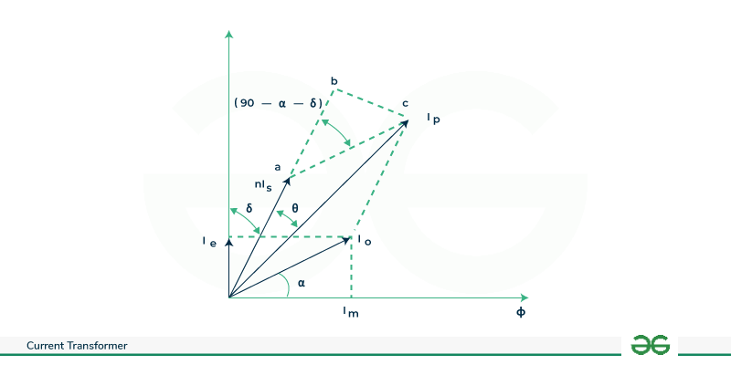
Phasor Diagram of Current Transformer
The can be calculated by using vector addition as we can it is the Phasor sum of the  and
and  (No load current).
So is:


So substitution the value of in the equation

![\begin{aligned} & R=\frac{\sqrt{\left[\left(n I_{s}\right)^{2}+\left(I_{0} \operatorname{Sin}(\alpha+\delta)\right)^{2}+\left(2 I_{o} n I_{s} \operatorname{Sin}(\alpha+\delta)\right]\right.}}{I_{s}} \\ & R=\frac{\sqrt{\left[n I_{s}+\left(I_{0} \operatorname{Sin}(\alpha+\delta)\right)\right]^{2}}}{I_{s}} \end{aligned}](https://quicklatex.com/cache3/43/ql_1925efe6801645400dd8d7016def3643_l3.png "Rendered by QuickLaTeX.com")


So ,from the equation we find that Transformation ratio is not equal to Turns ratio.For Transformation ratio to get equals to turns ratio and must be zero which can be only achieved in the ideal condition.
Phase Angle of Current Transformer
The phase angle of current Transformer is angle between primary current Ip and secondary current

Phasor Diagram of Current Transformer
In the given phasor diagram the Phase Angle of Current can be denoted by .Let us Assume a right angle triangle obc.
![\begin{aligned} \tan \theta & =\frac{b c}{o b} \\ & =\frac{I_{0} \operatorname{Sin}(90-\alpha-\delta)}{a \alpha+a b} \\ & =\frac{I_{0} \operatorname{Cos}(\alpha+\delta)}{\left[n I_{s}+I_{0} \operatorname{Sin}(\alpha+\delta)\right]} \end{aligned}](https://quicklatex.com/cache3/24/ql_60ddf14a7442e5202ec7ecdbbdd8d224_l3.png "Rendered by QuickLaTeX.com")
In CT there are two types of errors
- Ratio Error
- Phase angle Error
Ratio Error
As we know the current ratio and the turns ratio in CT should be equal  but due to magnetization and loss of components of primary side and power factor in the secondary which cause the difference between current ratio and the turns ratio.Due to this the actual current ratio will vary and it will depend upon load current and power factor of the load and due to this actual current ratio cannot be calculated. Ratio error can be expressed in terms of percentage.

Phase angle Error
As we Know Phase Angle of Current Transformer( ) is the angle between the primary current and the secondary current.The deviation in lead to Phase angle Error.
The load of the CT is generally resistive so the power factor is unity ( ) so now the equation for phase angle Error can be Written as
 Degree

 Degree
The the Errors in the CT can be reduced as:
- Proper Maintenance: By properly maintaining the transformer can not only can reduce Errors But it can also increase the health of the transformer.
- By reducing magnetizing and core loss component: Reducing the magnetizing and core loss current can lead to significant reduction in losses. To reduce this the material used in transformers must be highly permeable and core material should have less reluctance as possible.
- Shielding: By maintaining proper shielding in the transformer can protect the CT from external electromagnetic interference, which can introduce errors.
- Turn Compensation: Reducing the turns of the secondary winding can lead to a reduction in the actual ratio, which can be adjusted when the load is connected, making the nominal ratio equal.
Following are the Types of Current Transformers
- Indoor Current Transformers
- Outdoor Current Transformers
- Bushing Current Transformers
- Portable Current Transformers
Indoor Current Transformers
Current Transformers Which Designed For Indoor Environments are Known as Indoor current Transformers. They Have Very Compact Size which can used by Indoor Equipments for Medium to low Voltage Utilization. Indoor Current Transformers Have good Insulation with high Accuracy which makes theme Suitable for Indoor Environments.
Examples of Current Transformers are:
- Bar-Type CT: CT which has rectangular or circular type primary winding instead of traditional coil or winding.
- Ring Type: These are CT where slot or space is left in the centre to accommodate the primary conductor.
- Wound Type CT: In this CT the primary winding has multiple turns.
Outdoor Current Transformers
Outdoor current transformers are those that are specifically made to endure weather-related conditions and are engineered to survive elements like rain and UV radiation. They are commonly utilized for medium to high outdoor equipment. Outdoor current transformers provide accurate measurements even in challenging outdoor conditions.
Examples are:
- Mining CTs: These Types of CTs are specially designed for the mining areas.
- Railway Electrification CTs: They are designed for outdoor railway electrification systems.
- Switchyard CTs: These CTs are used in Switchyard for current measuring and monitoring purposes.
Bushing Current Transformer
Current Transformers which are desgined in form of bushing are known as Busing Current Transformers.They are Mounted on the buishing of the Equipment which make them compact and integral part of the overall system.They are used for relaying and measuring existing power transformers or circuit breakers.
Portable Current Transformers
As the name Suggest these types of Current Transformers are designed to be easily movable and are mostly used for temporary electrical measurments and Testing. They are Very much Flexible and used where Permanent Transformers Canoot be Installed.
Given below are the list of Advantages and Disadvantages of Current Transformers :
Advantages
- The CTs are used to measure High currents or high voltage lines Efficiently.
- The CTs have good Accuracy for measuring high currents.
- The CTs like Indoor Current Transformers are designed for compact areas and they don’t require large areas.
- The CTs have good isolation between primary and secondary side which increases its safety.
- The CTs have simple Design and also installation.
Disadvantages
- The CTs Requires Periodic maintenance to have good Accuracy which increases overall ownership cost.
- When current transformers (CTs) saturate, they lead to inaccurate readings and produce distorted waveforms, causing issues with relays and other equipment.
- The cost of manufacturing CTs are more as compared to other equipment like Shunt resistors.
- The CTs can be used to measure High currents.
- Current transformers (CTs) are used to measure electrical current and, together with other relays or devices, play a key role in detecting, asserting and monitoring the electrical system.
- CTs are used in in HVAC Systems to Monitor and Control Electrical Currents in motors and other Components.
- CTs can be Integrated with Renewable Energy Systems to measure Current generated by the Renewable Sources.
- CTs can be used with Industrial Automation Systems for Monitoring and Controlling Electrical Currents in Various Equipments and Machinery.
Conclusion
In conclusion, Current Transformers (CTs) play a crucial role in measuring high AC currents, providing a safe and efficient means of obtaining accurate readings. By utilizing the principles of electromagnetic induction, CTs step down high currents, allowing for safe transmission to measuring instruments, relays, or monitoring devices. While current transformers are essential for precise current measurement, careful consideration of their limitations and proper maintenance practices is necessary to ensure reliable and accurate performance in various applications.
1. What are the different Errors in CTs?
In CTs there are Two Types of Error which are Ratio error and Phase Angle Error.
2. Suggest some ways to reduce Errors in CTs ?
Some Of the ways to reduce Errors in Cts are by proper mantainence, By reducing magnetizing and core loss component, by shielding.
3. What are the different Types of CTs ?
Different Types of CTs are Indoor, Outdoor, Bushing, Portable Current Transformers.
Share your thoughts in the comments
Please Login to comment...