LED Control with Potentiometer using Arduino
Last Updated :
28 Mar, 2024
In the field of electronics and programming, controlling an LED with a potentiometer is important too. By varying the resistance of the potentiometer, you can change the brightness of the LED. We will interface an LED (light-emitting diode) to the Arduino UNO board. An LED is a simple diode that emits light with a forward bias. We control the brightness of an LED by interfacing a potentiometer with it. We write a program in the Arduino IDE and download it to the microcontroller board.
What is Arduino?
Arduino is an open-source, board that has a Microchip ATmega328P microcontroller on it. This microcontroller has a set of Digital and Analog input and output pins. The operating voltage of the board is 5V. It has 14 digital I/O pins & 6 Analog input pins. The clock frequency of the microcontroller is 16 MHz.
What is LED?
LEDs (Light Emitting Diodes) are becoming increasingly popular among a wide range of people. When a voltage is given to a PN Junction Diode, electrons and holes recombine in the PN Junction and release energy in the form of light (Photons). An LED’s electrical sign is comparable to that of a PN Junction Diode. When free electrons in the conduction band recombine with holes in the valence band in forward bias, energy is released in the form of light.
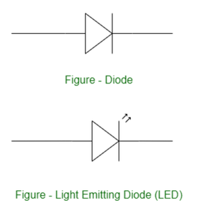
Light Emitting Diode
What is Potentiometer?
A potentiometer, sometimes known as a “pot,” is an electrical component used to manually alter the resistance in a circuit. It has three terminals and is a form of variable resistor. Potentiometer has many applications as it is used to control the volume of audio devices and change the brightness of screens or LEDs. We can regulate a parameter by varying the resistance over a wide range.
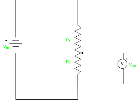
Potentiometer
Components Required
1. 1 X LED
2. 1 X Resistor, 330 Ohm
3. Breadboard
4. Arduino UNO R4 or earlier versions.
5. Jumper wires
6. Potentiometer
Components Description
- 1 X LED: We are controlling only one LED in this program.
- 1 X Resistor, 330 Ohm: For every LED, we need one current limiting resistor.
- Breadboard: A breadboard is a fundamental tool used in electronics and prototyping to build and test circuits without soldering.
- Arduino UNO R4 or earlier versions.
- Jumper wires: Jumper wires are simple electrical wires with connectors on both ends used to create connections between various electronic components or points on a circuit on a breadboard.
- Potentiometer: A potentiometer, sometimes known as a “pot,” is an electrical component used to manually change the resistance in a circuit.
Circuit Description and Working
The potentiometer, also known as a variable resistor, is attached to a circuit and allows the voltage to be varied by increasing or decreasing the resistance. We will utilize this variable resistance to adjust the brightness of the LED. For example, increasing the resistance will allow less current to reach the LED, causing it to glow less brightly. Similarly, lowering the resistance allows more current to be sent to the LED, causing it to glow brighter.
How to Perform for LED Control Using Potentiometer?
Following steps need to perform for LED control using potentiometer.
- Connect the longer pin (anode) of the LED to a resistor, and then connect the other end of the resistor to one of the Arduino’s digital I/O pin.
- Connect the shorter pin of the LED to the GND (ground) pin.
- Connect one end of the potentiometer to the 5V pin on the Arduino.
- Connect the other end of the potentiometer to the GND pin on the Arduino.
- Connect the middle pin of the potentiometer to an analog input pin (e.g., A0) on the Arduino.
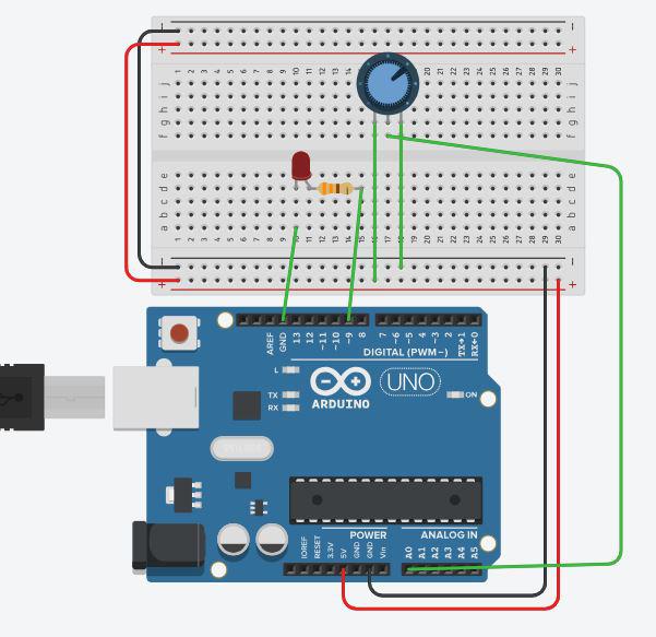
Circuit Diagram
Code
C++
int ledPin=9;
int potPin=A0;
int potValue;
int pinValue;
int DT=1000;
void setup()
{
  pinMode(ledPin, OUTPUT);
  pinMode(potPin, INPUT);
  Serial.begin(9600);
}

void loop()
{
  potValue=analogRead(potPin);
  Serial.println(potValue);
  delay(DT);
  pinValue=(255.0/1023.0)*potValue;
  analogWrite(ledPin,pinValue);
}
Code Analysis
- In the setup, you set the LED pin as an output and potPin as an input.
- In the loop, we need use the analogRead() function to read the analog voltage value from the potentiometer. This value will be between 0 and 1023, corresponding to the voltage applied to the potentiometer.
- Now we have to convert the potentiometer value (0-1023) to a suitable range for LED brightness (0-255).
pinValue = (255.0/1023.0)*potValue
or one can use direct map() function available in the Arduino library.
pinValue = map(potValue, 0, 1023, 0, 255);
- Finally, The analogWrite() function is used to regulate the brightness of the LED. It accepts values between 0 and 255, with 0 being off and 255 being full brightness.
Applications and Uses of LED control
Controlling the brightness of an LED with a potentiometer and an Arduino has various practical applications, particularly where changing light intensity is critical. Here are some of examples:
- Regulating Ambient Lighting: A potentiometer can be used to regulate LED strips or modules used for ambient lighting in rooms or displays.
- Display Screens Brightness: When creating projects that include screens (such as LED matrices, LCDs, or OLEDs), you may employ the potentiometer to regulate the backlight brightness of the display. This might help you adjust readability in different lighting situations.
- Photography lighting setups frequently involve the use of LEDs to generate numerous lighting effects. You may fine-tune the lighting parameters for better photographic results by regulating LED brightness using a potentiometer.
Conclusion
In conclusion utilizing a potentiometer with an Arduino to control LEDs provides a versatile and practical solution to modify brightness levels in a variety of applications. You may design dynamic lighting solutions that cater to user preferences, environmental conditions, and special project requirements by combining the capabilities of Arduino and the flexibility of potentiometers. This method provides for intuitive engagement, allowing users to manually fine-tune the intensity of LEDs to meet their specific demands. Controlling LED brightness adds a new degree of utility and efficiency to electrical projects, whether it’s for providing ambient lighting, altering display backlighting, or boosting visual effects.
FAQs on LED Control with Potentiometer Using Arduino
Q.1: What is the analogRead() function and how is it utilized in LED control?
Answer:
The Arduino function analogRead() reads the analog voltage on an analog input pin. analogRead() is used in LED control with a potentiometer to measure the position of the potentiometer's wiper, which sets the LED brightness level depending on the analog value acquired.
Q.2: Can I use a single potentiometer and Arduino to control numerous LEDs?
Answer:
Yes, you can control many LEDs by using the potentiometer to change the brightness of all LEDs at the same time. Connect the potentiometer to the Arduino's analogue input and use the potentiometer reading to control the brightness of all LEDs.
Q.3: How can I use a potentiometer to modify the LED brightness range?
Answer:
Using the map() method in Arduino, you may map the analogRead() values from the potentiometer (which range from 0 to 1023) to a desired brightness range (e.g., 0 to 255).
Share your thoughts in the comments
Please Login to comment...