In this Article, We will be going through Inductive Reactance, We will start the Article with the Introduction of Inductive Reactance, then we will go through Working and Reactance Theory, Then we will go through Inductor in Series and Parallel connection, At last, we will conclude our Article Phasor Diagram and Some FAQs.
What is Inductive Reactance?
An inductor is a passive device used to store energy in the form of a magnetic field across the inductor. An inductor behaves differently if it is placed in a circuit having a DC source or AC source. The inductor has the property to oppose sudden changes in current. When such abrupt change occurs, it tries to maintain the current flowing in the circuit by supplying the required current to the circuit. This current is generated by the magnetic field which was present when the inductor was charged. The magnetic field gets reduced after supplying the current. Inductance is measured in Henry named after Joseph Henry.

Structure of an inductor
Working of Inductor
When current flows through a conductor, a magnetic field is formed perpendicular to the direction of current flow. This magnetic field is across radial direction forming concentric circles of magnetic field lines. Right hand thumb rule can be used to identify the direction of magnetic field lines. When this conductor is wound into a coil, this individual magnetic fields are clubbed together to form a larger magnetic field across the whole coil. This coil is called as inductor and the magnetic field generates highly depends on the core material.

Magnetic field around a wire
The formula to calculate Inductance is
L = 𝜇N2A/l
Where L is inductance, 𝜇 is permeability of the core, N is the number of turns of coil and l is the length of coil.
According to Faraday’s law a changing electric field generates a changing magnetic field and vice versa. When AC current flows through the inductor, a time varying magnetic field is also generated. When the supply cuts off, the inductor supplys current since the magnetic field does not vanish immediately. This changing magnetic field creates the alternating current while consuming the magnetic field. Hence the inductor loses its magnetic field when external supply is removed and supplies AC for a short time with the help of this stored magnetic field.

Magnetic field around a coil
Reactance Theory
Reactance can be defined as opposition to the flow of alternating current inside passive components such as capacitor and inductor. Reactance is similar to resistance however resistance is not related to frequency of voltage or current in a circuit. Reactance changes with respect to frequency of voltage and current. Unlike resistance, reactance does not dissipate heat when it opposes the current. It opposes the current in different way. An inductor has both resistance and reactance, therefore requiring complex numbers to denote their values. Reactance in inductor is created due to current lagging the voltage by 90°. Normally the current and voltage follows Ohm’s law and are in phase with each other and vary linearly. This phase difference causes decrease in current through inductor when voltage across the inductor increases. This can be proved easily as follows:
We know, mangnetic flux present in the inductor is equal to inductance times current through the inductor. i.e.
Φ = Li
We also know, induced voltage is defined as change in magnetic flux per unit time according to faraday’s equation. i.e.
Vt = dΦ/dt
Subsituting Φ = Li,
Vt = Ldi/dt
It = ∫ V/L dt
∴ It = ∫ Vt dt/L [ ∵ L is constant ]
Let Vt = Vsin(ωt)
It = ∫ Vsin(ωt) dt/L
∴ It = -Vcos(ωt)/ωL [ ∵ ∫ sin(ωt)dt = -cos(ωt)/ω ]
There is a phase difference of -90° between sine and cosine function. Hence current I(t) lags voltage V by 90°.
At t = 0,
I0 = -V0cos(ω0)/ωL
I0 = -V0/ωL [ ∵ cos(0) = 1 ]
∴ V0/I0 = XL = 2𝜋fL [ ∵ ω = 2𝜋f ]
We can ignore the negative sign as it indicates current lagging. If we would have taken Vt as Vcos(ωt) then, It would have been Vtsin(ωt)/ωL indicating that voltage leads current by 90°.

Graph of current and voltage
Therefore Inductive reactance is equal to 2𝜋fL where, reactance is directly proportional to frequency of signal. This is the reason why inductor acts as closed switch in DC circuit since frequency of DC is 0 and hence reactance becomes zero. Hence in DC voltage, inductive reactance is very low. As freuqncy increases, inductive reactance increases. This behaviour of inductor is very useful to build filters to attenuate certain frequencies of signal. Inductive reactance is also directly proportional to inductance.
Inductors in Series And Parallel
Inductance and inductive reactance both changes when multiple inductors are introduced to the exisiting circuit. It changes based on how they are connected i.e. series or parallel. An equivalent inductance can be calculated when multiple inductors are connected in series or parallel to simplify the given circuit. The rules for combining the inductances are as follows:
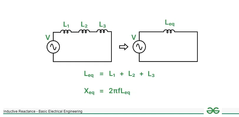
Inductors conned in series
When n inductors are connected in series, the total inductance of the circuit increases and is higher than the largest inductance provided by an individual inductor. It is equal to:
Leq = L1 + L2 + L3 + . . . + Ln

Inductors connected in parallel
When n inductors are connected in parallel, the total inductance of the circuit reduces and is lower than the least inductance provided by an individual inductor. It is equal to:
1/Leq = 1/L1 + 1/L2 + 1/L3 + . . . + 1/Ln
If we know the total inductance of the circuit, equivalent inductive reactance can be calculated as:
Xeq = 2𝜋fLeq
We can also find reactance of each inductor indivdually such as X1 = 2𝜋fL1 , X2 = 2𝜋fL2 , . . . , Xn = 2𝜋fLn and add those reactance if they are series or add their reciprocals if they are in parallel. i.e.

Reactance connected in series
For series, Xeq = X1 + X2 + X3 + . . . + Xn

Reactane connected in parallel
For parallel, 1/Xeq = 1/X1 + 1/X2 + 1/X3 + . . . + 1/Xn
Since reactance is the resistance provided by energy storing components such as capacitors and inductors, when multiple reactance are connected in series they are added directly and is higher than the largest reactance present in the circuit. When multiple reactances are connected in parallel, their reciprocals are added such that the total reactance is lower than the least reactance present in the circuit. These rules are same as resistors connected in series or parallel.
Graph of Reactance versus Frequency

Graph of reactance versus frequency
As we can clearly see that inductive reactance increases with increase in frequency as both are directly proportional to each other.
Phasor Diagram
A phasor diagram is the graphical representation of voltage and current for a given component in this case inductor. Phasor diagrams are used to check whether voltage and current are in phase or out of phase. It consists of two vectors representing voltage and current respectively. This vectors has length which is equal to the amplitude of the voltage and current and has an angle which is the angular frequency of the AC signal. We can graphially verify that current lags voltage by 90° in an inductor.

Phasor diagram of inductor
Solved Examples
An inductor having inductance 0.1 mH is connected to supply whose frequency is 1 MHz. Find the inductive reactance.

Circuit diagram for 1st sum
XL = 2𝜋fL
f = 1 MHz = 1 × 10⁶ Hz
L = 0.1 mH = 1 × 10⁻³ H
∴ XL = 2𝜋 × 103 = 6.28 KΩ
An inductor is constructed using thin metal wire wounded 11 times around a magnet having relative permeability of 102 and the radius of each loop is 5 mm. The length of the inductor after wounding is 5cm. This inductor is connected to a frequency generator generating a sine wave of frequency 50 KHz. Find the inductive reactance which will be provided by the inductor.

Circuit diagram for 2nd sum
N = 11
𝜇0 = 4𝜋 × 10-7, 𝜇r = 102
𝜇 = 𝜇0𝜇r
∴ 𝜇 = 1.28 × 10⁻⁴
r = 5 mm = 5 × 10⁻³ m
A = 𝜋r2
∴ A = 7.85 × 10⁻⁵ m2
l = 5 cm = 5 × 10⁻² m
L = N2𝜇A/l
∴ L = 2.43 × 10⁻⁵ H
f = 50 KHz = 50 × 103 Hz
XL = 2𝜋fL
∴ XL = 7.65 Ω
Three inductors having inductances 1 mH, 2 mH and 3 mH are connected in parallel such that their equivalent inductive reactance is equal to 10 KΩ. Find the frequency of the signal which was passed through this circuit.

Circuit diagram for 3rd sum
L1 = 1 mH = 1 × 10⁻³ H, L2 = 2 mH = 2 × 10⁻³ H, L3 = 3 mH = 3 × 10⁻³ H
1/Leq = 1/L1 + 1/L2 + 1/L3
1/Leq = 5500/3
Leq = 5.45 × 10⁻⁴ H
Xeq = 10000 Ω
Xeq = 2𝜋fLeq
∴ f = Xeq/2𝜋Leq
f = 2.91 MHz
Conclusion
We have gone through the concept of inductive reactance, starting with an introduction to inductors and their behavior in circuits. We discussed the working principles of inductors, reactance theory, and how inductors behave in series and parallel connections. Additionally, we examined the graph of reactance versus frequency and learned how to represent inductive reactance in phasor diagrams and we have also gone through the Solved Examples.
FAQs on Inductive Reactance
What is impedance?
The sum of all reactance and resistance present in a circuit is called as impedance and is represented by Z. For a purely resistive circuit, impedance Z is equal to equivalent resistance of the circuit Req. Impedance is an important parameter which describes how much current will the circuit draw from the voltage source.
What is mutual inductance?
Mutual inductance is a property in which an inductor controls the voltage and current flow in another inductor which is placed near by. This happens due to coupling of magnetic fields induced by both inductors. This principle is used in transformers to increase or decrease AC voltage respectively.
Does transformer have reactance?
Yes transformer has both resistance and reactance. This causes the output voltage of the transformer to reduce when a load is connected across the ooutput terminals of the transformer. There is also reactance present in the primary side which causes some voltage to drop before is it stepped up or stepped down.
Share your thoughts in the comments
Please Login to comment...