In this article, we will be going through Capacitive Reactance, First we will start our Article with the Introduction of the Capacitor, then we will go through the Working of the Capacitor and Reactance Theory, and Then we will go through Capacitors in parallel and Series Circuit, At last, we will conclude our Article with Comparison of Capacitive and Inductive Reactance, Applications, Solved Examples and Some FAQs.
What is Capacitive Reactance?
Capacitive reactance is the opposition presented by a capacitor to the flow of alternating current (AC) in a circuit. Unlike resistance, which remains constant regardless of frequency, capacitive reactance varies with the frequency of the AC signal. It is denoted by the symbol XC and is measured in ohms (Ω).
The Formula for Capacitance Reactance(XC) can be given as

- f is the frequency of the AC signal,
- c is the capacitance of the capacitor.
What is Capacitor?
A capacitor is a passive device used to store electric energy in the form of an electric field between two parallel plates of conductors which are separated by a dielectric material. Dielectric materials are those materials which has the capacity to store electric charges. A capacitor behaves differently if it is placed in a circuit having a DC source or AC source.
The capacitor has the property to oppose sudden changes in voltage. When such abrupt change occurs, it tries to maintain the voltage by supplying the required voltage to the circuit. This voltage is generated by the electric field which was present when the capacitor was charged. The electric field gets reduced after supplying the voltage. This behaviour of the capacitor is useful and is used in power supplies to regulate the output DC voltage. Capacitance is measured in Farads named after Michael Faraday.
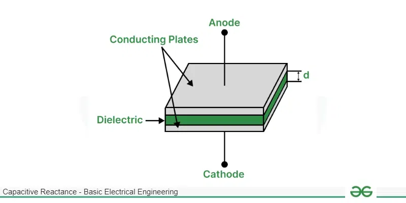
Capacitor
Working of Capacitor
A capacitor consists of two metal plates separated by some dielectric material such as air or paper. It is possible to store charges on these metal plates with the help of external power source. When a battery is connected to a capacitor as shown in the above figure, electrons are pumped out of the battery and reaches the right side metal plate and accumulates there since it is attracted by the holes (positive) which is provided by positive terminal of the battery. The electrons stored in the metal plate cannot reach the other plate since it is separated by the dielectric. This electric field is still maintained even after disconnecting the battery.
The ability to hold charges is called capacitance and it depends on the area of the metal plate, since higher area means more electrons can be accumulated. It also depends on distance between the plates, since electrostatic forces are weak and to attract more electrons to the plate, there must be strong positive force at the other side of the metal plate and this force reduces as the distance increases. It also depends on the dielectric constant of the material placed between the metal plates.
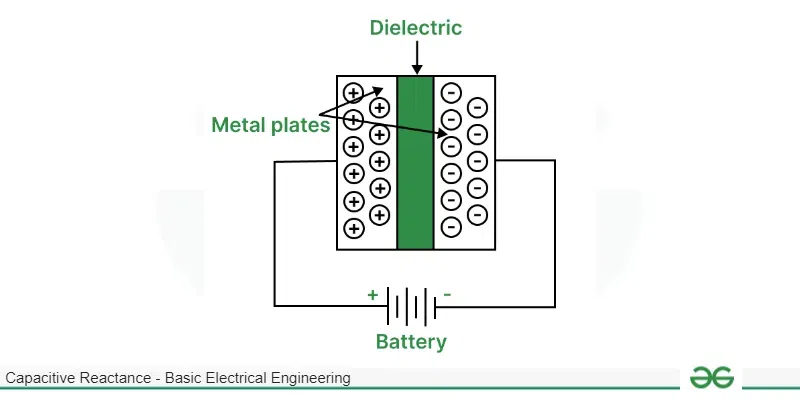
Working of Capacitor
The formula to calculate Capacitance is
C = 𝜀A/d
Where C is capacitance, ε is permittivity of the dielectric and d is the distance between the two electrodes.
When AC supply is connected, the charges are still stored in the capacitor but the polarity of the voltage changes with time. Current does not flow through the capacitor once it is charged to the source voltage like in the case of DC supply. However the changing polarity causes the current to flow through the capacitor since the capacitor charges and discharges continuously.
Reactance can be defined as opposition to the flow of alternating current inside passive components such as capacitor and inductor. Reactance is similar to resistance however resistance is not related to frequency of voltage or current in a circuit. Reactance changes with respect to frequency of voltage and current.
Unlike resistance, reactance does not dissipate heat when it opposes the current. It opposes the current in different way. A capacitor has both resistance and reactance, therefore requiring complex numbers to denote their values. Reactance in capacitor is created due to current leading the voltage by 90°.
Normally the current and voltage follows Ohm’s law and are in phase with each other and vary linearly. This phase difference cause decrease in current through capacitor when voltage across the capacitor increases. This can be proved easily as follows:
We know, charge present in the capacitor is equal to capacitance times voltage across the capacitor. i.e.
Q = CV
We also know, current is defined as flow of charges per unit time. i.e.
It = dQ/dt
Substituting Q = CV,
It = CdVt/dt
Let Vt = Vsin(ωt)
It = CdVsin(ωt)/dt
∴ It = CVωcos(ωt) [ ∵ dsin(ωt)/dt = ωcos(ωt) ]
There is a phase difference of 90° between sine and cosine function. Hence current i(t) leads voltage V by 90°.
I0 = CV0ωcos(ω0)
I0 = CV0ω [ ∵ cos(0) = 1 ]
∴ V0/I0 = Xc = 1/2𝜋fC [ ∵ ω = 2𝜋f ]
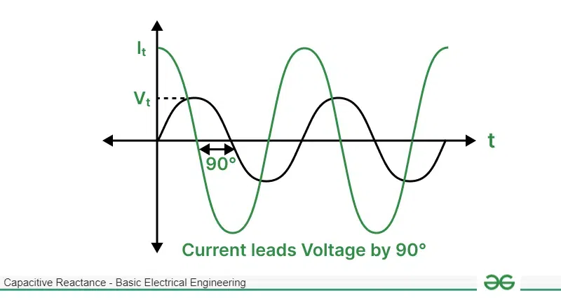
Graph of Current and Voltage
Therefore Capacitive reactance is equal to 1/2𝜋fC where, reactance is inversely proportional to frequency of signal. This is the reason why capacitor acts as open switch in DC circuit since frequency of DC is 0 and 1/0 becomes infinite. Hence in DC voltage, capacitive reactance is very high. As frequency increases, capacitive reactance decreases. This behaviour of capacitor is very useful to build filters to attenuate certain frequencies of signal. Capacitive reactance is also inversely proportional to capacitance.
Capacitors in Series and Parallel
Capacitance and capacitive reactance both changes when multiple capacitors are introduced to the existing circuit. It changes based on how they are connected i.e. series or parallel. An equivalent capacitance can be calculated when multiple capacitors are connected in series or parallel to simplify the given circuit. The rules for combining the capacitances are as follows:
Capacitors Connected in Series
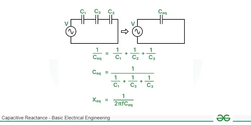
When n capacitors are connected in series, the total capacitance of the circuit reduces and is lower than the least capacitance provided by an individual capacitor. It is equal to:
1/Ceq = 1/C1 + 1/C2 + 1/C3 + . . . + 1/Cn
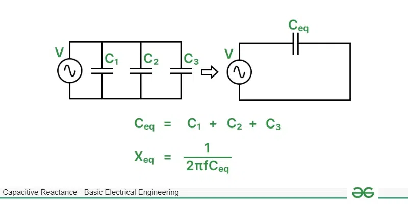
Capacitor in Parallel Circuit
When n capacitors are connected in parallel, the total capacitance of the circuit increases and is higher than the largest capacitance provided by an individual capacitor. It is equal to:
Ceq = C1 + C2 + C3 + . . . + Cn
The equivalent capacitive reactance can be calculated as if we know the total capacitance of the circuit,
Xeq = 1/2𝜋fCeq
We can also find reactance of each capacitor indivdually such as X1 = 1/2𝜋fC1 , X2 = 1/2𝜋fC2 , . . . , Xn = 1/2𝜋fCn and add those reactance if they are series or add their reciprocals if they are in parallel. i.e.
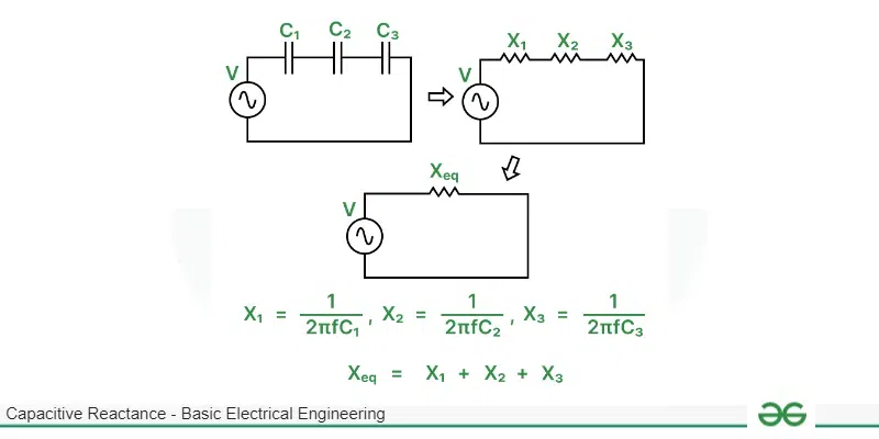
Reactance connected in Series
For series, Xeq = X1 + X2 + X3 + . . . + Xn
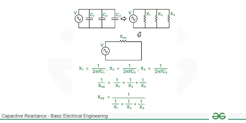
Reactance Connected in Parallel
For parallel, 1/Xeq = 1/X1 + 1/X2 + 1/X3 + . . . + 1/Xn
Since reactance is the resistance provided by energy storing components such as capacitors and inductors, when multiple reactance are connected in series they are added directly and is higher than the largest reactance present in the circuit. When multiple reactance are connected in parallel, their reciprocals are added such that the total reactance is lower than the least reactance present in the circuit. These rules are same as resistors connected in series or parallel.
Graph of Reactance Versus Frequency
Given Below is the graph for the Reactance Versus Frequency
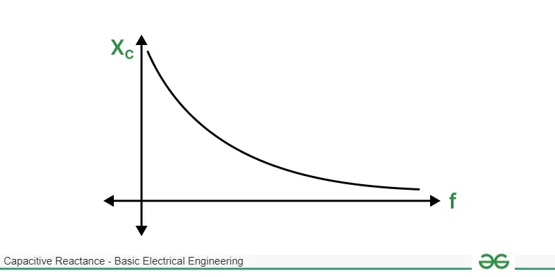
Graph of Reactance Versus Frequency
From the above graph we can confirm that as the frequency increases, capacitive reactance decreases since capacitive reactance is inversely proportional to frequency.
Comparison of Capacitive and Inductive Reactance
Capacitive Reactance
| Inductive Reactance
|
|---|
In capacitive reactance, current leads voltage by 90°.
| In inductive reactance, current lags voltage by 90°.
|
Capacitive reactance can be given by the formula XC = 1/2𝜋fC.
| Inductive reactance can be given by the formula XL = 2𝜋fL.
|
Capacitive reactance decreases with increase in frequency.
| Inductive reactance increases with increase in frequency.
|
When capacitive reactance is represented as complex number, the imaginary part is negative.
| When inductive reactance is represented as complex number, the imaginary part is positive.
|
Due to capacitive reactance, capacitors are used in high pass filters since attenuation is less for high frequency signals.
| Due to inductive reactance, inductors are used in low pass filters since attenuation is less for low frequency signals.
|
Applications on Capacitive Reactance
Given Below is the Application of the Capacitive Reactance
- Since reactance opposes the flow of current without dissipating the excess current as heat, capacitors are mainly used in regulators to control the speed of fan as the frequency is constant i.e. 50Hz and the value of capacitance can be changed to vary the capacitive reactance. As capacitance and capacitive reactance are inversely proportional, higher capacitance provides higher fan speed.
- Capacitor are also used in passive high pass filters which are constructed along with some resistors and their cost is low. Here, the capacitance is fixed and the frequency is varied which produces different reactance. Such high pass filters block low frequency signals. However their draw is that they do not have sharp cut-off frequencies i.e. reactance changes proportionally with frequency hence low frequency signals are not completely attenuated.
- As we already mentioned, reactance causes the power to be stored for certain time and supplies this power for some time period when there is sudden loss of power in the circuit. This is used to smoothen the DC output provided by various rectifier circuits as it fills sudden dips and cuts off any peaks in the output.
- As reactance can also be negative, capacitive reactance is usually combined with inductive reactance to cancel each other and transfer maximum power since circuit becomes purely resistive.
Solved Examples on Capacitive Reactance
Example 1
A capacitor having capacitance 100𝜇F is connected to supply whose frequency is 1MHz. Find the capacitive reactance.
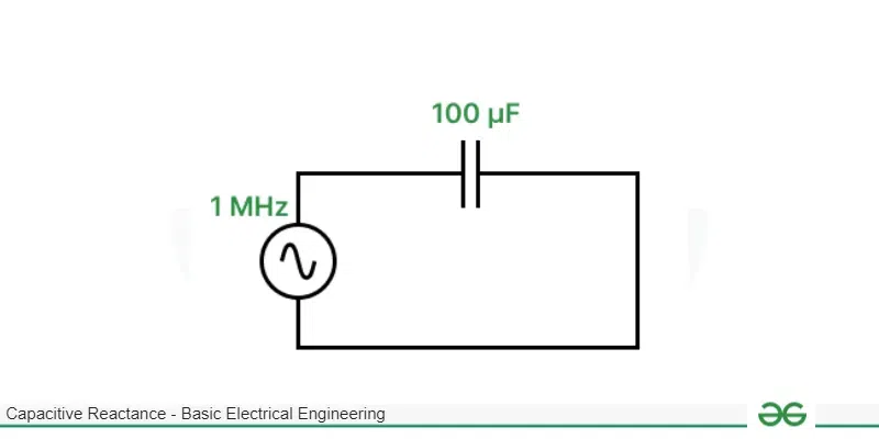
Circuit Diagram for 1st sum
XC = 1/2𝜋fC
f = 1 × 10⁶
C = 1 × 10⁻⁶
∴ XC = 1/2𝜋 = 0.159 Ω
Example 2
A capacitor is built using two metal plates having area equal to 20mm2 separated by 0.1mm which contains air. This capacitor is connected to a frequency generator generating a sine wave of frequency 200KHz. Find the capacitive reactance which will be provided by the capacitor.
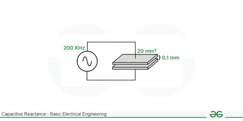
Circuit diagram for 2nd sum
C = 𝜀A/d
𝜀 = 8.85418782 × 10⁻¹²
A = 20mm2 = 20 × 10-6
d = 0.1mm = 0.1 × 10⁻³
∴ C = 1.77 × 10⁻¹² F
XC = 1/2𝜋fC
XC = 449.59 KΩ
Example 3
Three capacitors having capacitances 10 𝜇F, 20 𝜇F and 30 𝜇F are connected in parallel such that their equivalent capacitive reactance is equal to 145 KΩ. Find the frequency of the signal which was passed through this circuit.
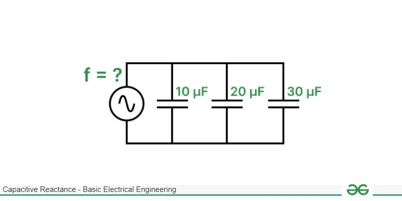
Circuit Diagram for 3rd sum
Ceq = C1 + C2 + C3
Ceq = 10 + 20 + 30 = 60 × 10-6 F
Xeq = 1/2𝜋fCeq
Xeq = 145000 Ω
∴ f = 2𝜋XeqCeq
f = 54.66 Hz
Conclusion
In this Article we will gone through capacitive reactance, capacitive reactance is a Important concept in electronics, governing how capacitors work in circuits. It resists changes in voltage, becoming weaker as the frequency increases. It has Various Applications like controlling fan speeds and filtering signals. Unlike inductive reactance, it leads voltage by 90° and shrinks with higher frequencies. . Capacitors, essential parts of electronics, rely on this property for stability and storing energy. Understanding capacitive reactance is key to building efficient and dependable electrical systems.
FAQs on Capacitive Reactance
What is impedance?
The sum of all reactance and resistance present in a circuit is called as impedance and is represented by Z. For a purely resistive circuit, impedance Z is equal to equivalent resistance of the circuit Req. Impedance is an important parameter which describes how much current will the circuit draw from the voltage source.
What is resonant frequency?
A circuit consists of inductors and capacitors. As frequency is directly proportional to inductive reactance, it becomes quite high at microwave frequencies. Also capacitive reactance is inversely proportional to frequency. It becomes high at low frequency. The frequency at which inductive reactance is equal to capacitive reactance is called as resonant frequency as the circuit becomes purely resistive and impedance is least at this frequency.
How to represent impedance?
Impedance can be represented in both cartesian form and polar form. For inductor having reactance 100 Ω, impedance is represented as 100 ∠90° in polar form and 0 + 100j in cartesian form. For capacitor having reactance 100 Ω, impedance is represented as 100 ∠-90° in polar form and 0 – 100j in cartesian form. Rules for conversion are as follows:
Cartesan = x + iy and Polar = z ∠𝛳
To convert, cartesian form to polar form:
z = (x2 + y2)1/2 and 𝛳 = tan-1(y/x)
To convert, polar form to cartesian form:
x = zcos(𝛳) and y = zsin(𝛳)
Share your thoughts in the comments
Please Login to comment...