Inductors are electrical components that create a magnetic field when an electric current is passed through them. Inductors are most commonly coil-like structures in electronic circuits that are mostly used to reduce or control electrical spikes in a circuit. There are various types of inductors including, Iron Core and Air Core Inductors. Its main functions include controlling signals and storing energy.
In this article, we will study Inductors, Types of Inductors, Functions, and Construction of Inductors, Energy stored in Inductors along with the Inductors in parallel and series, and a brief difference between inductors and capacitors.
What is an Inductor?
Inductor is a passive electronic component which stores energy in the form of a magnetic field. In simple words, an inductor consists of just a wire loop or coil that is used to control electric spikes by temporarily storing energy and then releasing it back into the circuit through an electromagnetic field.
Inductance is directly proportional to the number of turns in the coil. It also depends on other things such as the radius of the coil and the type of material around which the coil is wound.
Inductor is made of a wire whose property is inductance, i.e. it opposes the flow of current. The inductance of the wire increases when the number of turns is increased. Inductance is represented by the alphabet ‘L’ and it is measured in Henry. The formula of Inductance can be given by the ratio of flux and the current in the circuit. It is represented as:
L = Φ/I
where,
- L is Inductance
- Φ is Flux
- I is Current
Inductor Unit
Unit of inductance is 1 henry (H). The unit is symbolized by the letter H. An inductor be a passive electronic component that is more often used to gain energy in form of magnetic field. This is a measure of amount of energy stored in an inductor, which depends on the amount of inductance.
Inductor Symbol
In circuit diagrams, an inductor is represented by a coil or loops. It typically looks like a series of several closely spaced loops or a coil of wire, often with two terminals, as shown below:

The ends of the symbol normally indicate the terminals where an inductor can be connected to a circuit.
Inductor Formula
The voltage (V) across an inductor is directly proportional to the rate of change of current (I) flowing through it:
V(t) = L dI(t)/dt
Where:
- V(t) is the inductive voltage at time t
- L is the inductor inductance
- dI(t)/dt denotes the speed of change of current over time ‘t’
Inductor Reactance
Inductor reactance refers to the way an inductor behaves in AC circuits. Reactance is a characteristic measure of the opposition that an inductor gives to the changing flow of current.
The reactance X L of an inductor is given by the following formula:
XL = 2πfL
Where,
- XL is the inductive reactance (in ohms, Ω).
- f is the frequency of an AC signal measured in hertz, Hz.
- L is the inductance of inductor.
Construction of an Inductor
Construction of an inductor consists of a coil that is formed by twisting wire into circles wrapped around a core and is used to store energy in a magnetic field while electricity runs through it.
First, construct a coil of good conducting material usually copper wire is used for this. This core is then wrapped around a plastic or ferromagnetic material called a core. Number of twists of the wire raises the induction value and the use of ferromagnetic material also ensures high permeability which results in higher inductance value. The loose ends of the wire can be further connected to wires or devices, making it simpler for them to join with electronics. Inductors are formed in various shapes and sizes depending upon the requirement of the device.
Below is a simple diagrammatic explanation of the construction of a simple inductor.

Different Types of Inductors
The different types of inductors include the following:
- Iron Core Inductor
- Coupled Inductor
- Air Core Inductor
- Iron Powder Inductor
- Variable Inductor
- Ferrite Core Inductor
- Choke
A detailed explanation for a few of them is given below:
Iron Core Inductor
Iron core inductors are made of iron and are normally used in high-power inductors, but they are limited in high-frequency capacity. They are used in places where low space inductors are required because being low space inductors, they have high inductance value when compared to air core conductors. Also, there is a significant energy loss in the process. These inductors are widely used in audio equipment.
Air Core Inductor
Air Core Inductors are hollow and are normally used in applications where the level of inductance requirement is very low. The fact that no core is used ensures there are no losses within the core and the coil is supported by the air.
These types of Inductors are effective in high-frequency settings. The core of these conductors is made up of plastic, or ceramic and so they are also known as ceramic conductors.
Iron Powder Inductor
An Iron Powder Inductor is an inductor that uses compressed iron powder in its core. This core material makes it possible to create a magnetic field around the inductor so that when an electric current runs through it, energy is stored in the form of a magnetic field.
These inductors have the ability to give relatively high values of inductance for their size and are well-suited for all types of electronic products where space and cost need consideration. These inductors are also used in power supplies, filters, and radio frequency circuits.
Ferrite Core Inductor
Ferrite Core Inductors use a rod or core made from a ferric material. The two main components of these inductors are the ferrite core and the winding. The most common material used in ferrite core inductors is ferromagnetic material which increases the formation of a magnetic field thus providing a higher inductance value.
Ferrite core inductors are further classified into two types namely soft ferrites and hard ferrites.
Choke
A choke inductor, more commonly called a “choke,” is an electrical component used chiefly for choking off or blocking alternating current (AC) while allowing direct current(DC) to pass with relatively little resistance. This sort of inductor has a high impedance to AC signals, so it effectively filters or isolates them from circuits.
Chokes are most commonly used in electronic circuits for filtering and noise suppression as well as to separate AC and DC signals.
Functions of an Inductor
Inductors are most commonly used to perform the following functions:
- Controlling Signals
- Storing Energy
Controlling Signals
Controlling signals is one of the primary functions of an inductor. It is used to handle electric or digital signals to get specific results, like changing frequency and filtering them.
The frequency of the current passing in an inductor plays a vital role in controlling the signals within an inductor. It is helpful in blocking AC and allows the DC to pass through it. This is possible because higher frequency symbols are passed easily inside an inductor thus allowing DC currents to pass through them easily.
Storing Energy
In an inductor, the core is used to store energy. Inductors store energy in the form of magnetic fields. Energy storage is the process of adding and maintaining power to a system or gadget for future use. This aids in managing, balancing, and controlling the energy consumption of many systems, including buildings and automobiles.
Inductors in Parallel Form
Inductors in parallel are the network of inductors that are connected together with the same two nodes in a circuit. This setup is similar to the connections of resistors in parallel. When connected in parallel the voltage across each inductor remains the same, however, the current in each inductor will be different. The maximum opposing inductor will receive the minimum current.
The total inductance of all the inductors connected in parallel will always be less than the individual inductance present in the circuit. The total current in the circuit is the sum of current in each inductor. The total inductance in the circuit increases or decreases according to the amount of magnetic coupling between the coils.
The diagrammatic representation for the inductors connected in parallel is given below:

The total inductance in the circuit where inductors are connected in parallel is given by the formula:
[Tex]\frac{1}{L_T} = \frac{1}{L_1} + \frac{1}{L_2} + …..+ \frac{1}{L_n}
[/Tex]
The derivation of the above-mentioned formula is explained below:
The total current in the circuit is given by:
IT = I1 + I2 + I3 + ……..+ In
We know that the formula for voltage across an inductor is given by,
[Tex]V = L \frac{di}{dt}
[/Tex]
we can write,
[Tex]V_T = L_T \frac{di}{dt}
[/Tex]
[Tex]V_T = L_T \frac{d(I_1 + I_2 +…+I_n)}{dt}
[/Tex]
[Tex]V_T = L_T (\frac{dI_1}{dt} +\frac{dI_2}{dt} + …. + \frac{dI_n}{dt}
[/Tex]
Substituting V / L in place of di/dt, we get
[Tex]V_T = L_T (\frac{V}{L_1} + \frac{V}{L_2} +….+ \frac{V}{L_N})
[/Tex]
∴ We know VT = V, and the equation reduces to
[Tex]\frac{1}{L_T} = \frac{1}{L_1} + \frac{1}{L_2} + …..+ \frac{1}{L_n}
[/Tex]
Also Check, Resistance in Parallel and Series
Inductors in Series
The inductor in Series refers to the network of inductors connected end-to-end so that there is only one path for the flow of electric current. The current flowing in each inductor remains the same but the voltage drop in each inductor is different.
When inductors are put together end-to-end in an electrical circuit, their individual amount of inductance add up to make one total degree of induction. This means that all the inductors connecting together in a series make a stronger impact than any one inductor alone.
Representation of inductors connected in series is given below:
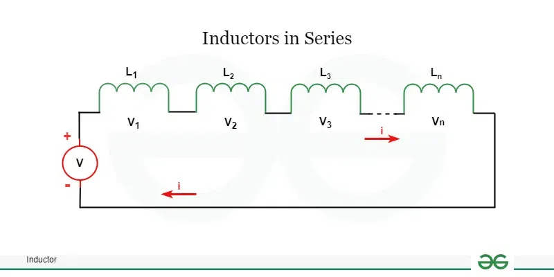
Total inductance in the circuit where inductors are connected in series is given by the formula:
LT = L1 + L2 + ……+ Ln
We know that in series the current is equal in each branch. That is,
IT = I1 = I2 = … = In
Total voltage in the circuit is given by:
VT = V1 + V2 + ….. + Vn
We know that the formula for voltage across an inductor is given by,
[Tex]V = L \frac{di}{dt}
[/Tex]
we can write,
[Tex]V_T = L_T \frac{di}{dt}
[/Tex]
[Tex]L_T \frac{dI_T}{dt}= L_1 \frac{dI_1}{dt} + L_2 \frac{dI_2}{dt} + ….+ L_n \frac{dI_n}{dt}
[/Tex]
But here, IT = I1 = I2 = … = In
So, the equation reduces to
[Tex]L_T \frac{dI_T}{dt}= (L_1 + L_2 + ….+ L_n) \frac{dI_T}{dt}
[/Tex]
Hence, the total inductance is given by LT = L1 + L2 + ……+ Ln
Also Check,
Energy Stored in an Inductor
When electric current flows through an inductor, electrical energy is stored in it. An inductor stores this electrical energy in the form of magnetic energy. The amount of electrical energy an inductor can store depends on its inductance and the magnitude of the electric current flowing through it.
The following formula can determine the electrical energy stored by an inductor.
E = LI2/2
where,
- E is Amount of Stored Energy
- L is Inductance of Inductor
- I is Electric Current Flowing in Inductor
Impedance of an Inductor
Impedance of an inductor is a measure of the resistance offered by the alternating current (AC) passing through a circuit. In simple words, Impedance can be referred to as the opposition to the current passing in a circuit. Usually, it is denoted by ‘Z’. The standard measure for inductance is Ohm (Ω).
The formula for an inductor’s impedance is:
Z = jωL
where,
- Z is Impedance of the inductor
- j is an imaginary unit
- ω is the angular frequency of the AC signal
- L is the inductance of the coil in Henry
Difference Between Inductor and Capacitor
The key difference between an inductor and a capacitor is given below:
Inductor VS Capacitor
|
|---|
Inductor
| Capacitor
|
|---|
| Inductors resist change in current. | Capacitor resists changes in voltage. |
| Energy is stored in the form of a Magnetic Field. | Energy is stored in the form of an Electric Field. |
| The SI unit of Inductance is Henry. | The SI unit of Capacitance is Farad. |
| Current lags the voltage by π/2. | Voltage lags the current by π/2. |
| They provide the best efficiency at low frequencies. | They provide the best efficiency at high frequencies. |
Read More,
Inductor – FAQs
What is an inductor?
An inductor is a passive electronic component that stores energy in a magnetic field when electric current flows through it. It typically consists of a conductor, such as a wire, wound into a coil.
How does an inductor work?
When current flows through the coil of an inductor, a magnetic field is generated around it. This field stores energy. If the current changes, the magnetic field changes, inducing a voltage opposite to the change in current, based on Lenz’s Law.
What is the Value of Power Factor for a Pure Inductor?
The power factor for a pure inductor value is always zero.
What is Self-Induction?
Self-induction is a type of induction in which a coil tends to resist changes in current in itself.
What is Mutual Induction?
When changing current in one coil induces an emf in the other coil, the phenomenon is called mutual induction. The strength of the induced emf depends on the mutual inductance of the pair of coils.
When is EMF Induced in a Circuit?
An EMF is induced in a circuit when there is a change in the magnetic flux passing through it.
Why does an inductor block AC but allow DC?
An inductor blocks AC because it resists changes in current flow. For DC, once the initial electromagnetic field is built up, there is no change in current, so the inductor behaves almost like a short circuit, allowing DC to pass through with minimal resistance.
What factors affect the inductance of a coil?
Several factors influence the inductance of a coil:
- The number of turns in the coil.
- The material of the core (ferromagnetic materials increase inductance).
- The shape and size of the coil.
- The presence of a core material within the coil.
What are the types of inductors?
There are various types of inductors, each suited for different applications:
- Air-core inductors, which do not use a magnetic core.
- Iron-core inductors, which have a ferromagnetic core to enhance the magnetic field.
- Toroidal inductors, which are wound on a doughnut-shaped core.
- Ferrite beads, used in electronic circuits to suppress high-frequency noise.
What is the function of an inductor in an AC circuit?
In AC circuits, inductors are used to block higher frequencies while allowing lower frequencies to pass. They are commonly used in filters, like those in audio and radio frequency applications.
What is the Use of Inductor?
Inductors are mainly used in electrical power and electronic devices to Chok, block, or filter high frequency noise in electrical circuits.
What is Principle of an Inductor?
The concept of an inductor is its ability to hold energy in the form of magnetic field when the electric current flows through it.
What is the SI Unit of Inductors?
SI unit of inductance is Henry which is represented as ‘H’.
Share your thoughts in the comments
Please Login to comment...