Implementation of VLSM in Cisco
Last Updated :
26 Apr, 2024
Pre-requisite: Introduction of Variable Length Subnet Mask (VLSM)
VLSM is a Variable Length Subnet Mask in which the subnet design uses more than one mask in the same network which means more than one mask is used for different subnets of a single class A, B, C, or a network. It is used to improve the usability of subnets as they can be of variable size. It is also defined as the process of subnetting a subnet.
Steps:
Step 1: First, open the cisco packet tracer desktop and select the devices given below:
| S.NO |
Device |
Model-Name |
Qty. |
| 1. |
pc |
pc |
3 |
| 2. |
switch |
PT-Switch |
3 |
| 3. |
router |
PT-Router |
3 |
IP Addressing Table for PCs
| S.NO |
Device |
IPv4 Address |
Subnet-Mask |
Default-Gateway |
| 1. |
pc0 |
192.168.10.2 |
255.255.255.192 |
192.168.10.1 |
| 2. |
pc2 |
192.168.10.66 |
255.255.255.224 |
192.168.10.65 |
| 3. |
pc4 |
192.168.10.98 |
255.255.255.252 |
192.168.10.97 |
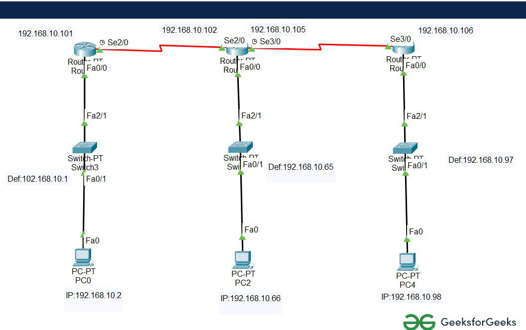
- Then, create a network topology as shown below the image.
- Use an automatic connecting cable to connect the devices with others.
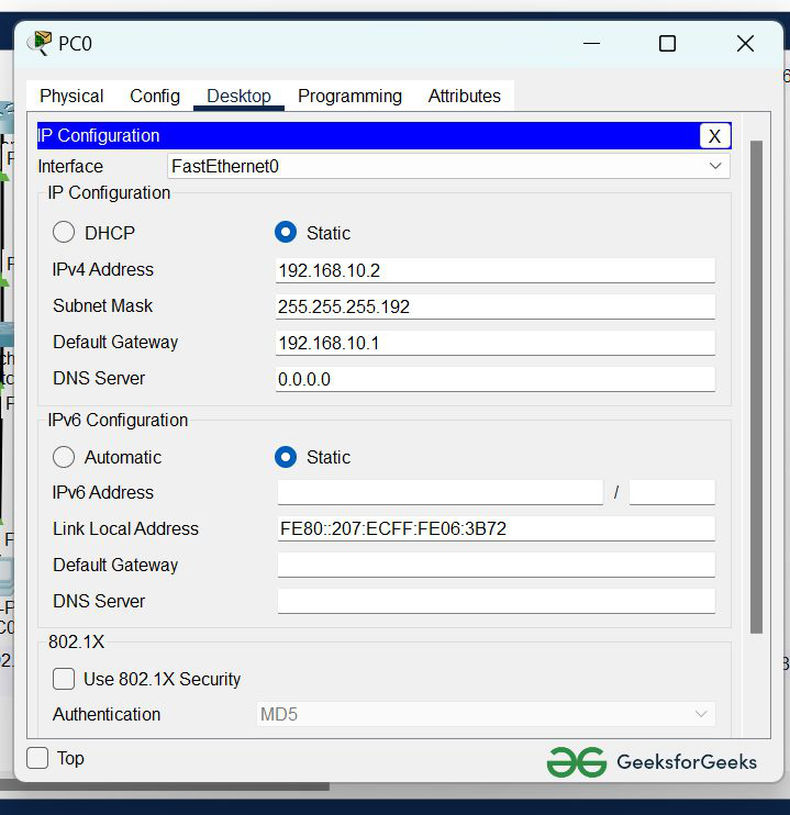
Step 2: Configure the PCs (hosts) with IPv4 address and Subnet Mask according to the IP addressing table given above.
- To assign an IP address in PC0, click on PC0.
- Then, go to desktop and then IP configuration and there you will IPv4 configuration.
- Fill IPv4 address and subnet mask.
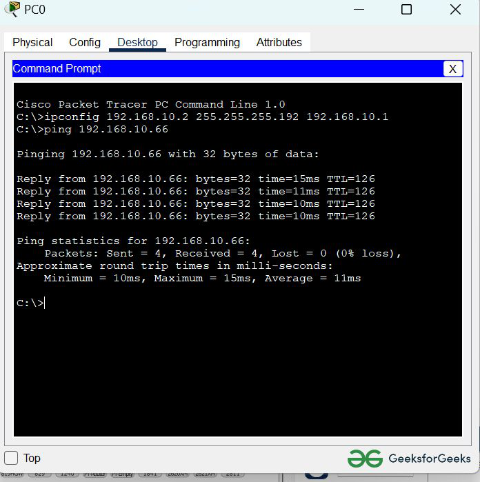
- Assigning an IP address using the ipconfig command, or we can also assign an IP address with the help of a command.
- Go to the command terminal of the PC.
- Then, type ipconfig <IPv4 address><subnet mask><default gateway>(if needed)
Example: ipconfig 192.168.10.2 255.255.255.192 192.168.10.1
- Repeat the same procedure with other PCs to configure them thoroughly.
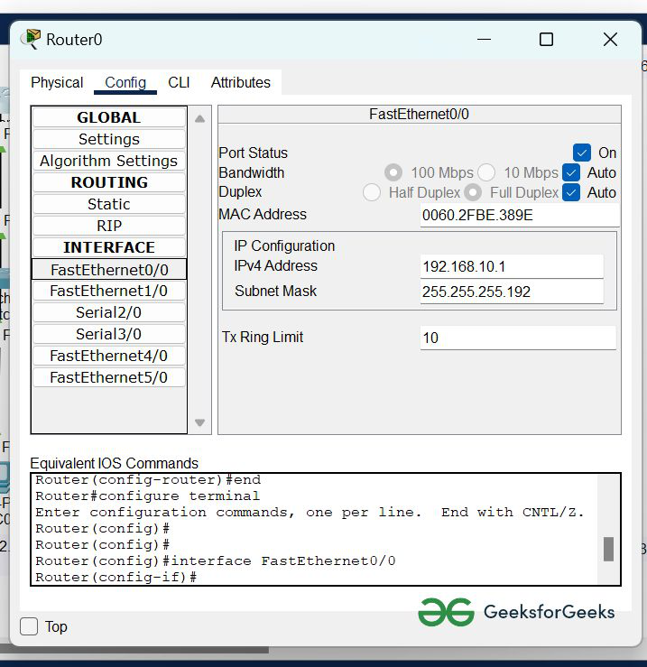
Step 3: Configure router with IP address and subnet mask.
| S.NO |
Device |
Interface |
IPv4 Address |
Subnet mask |
| 1. |
router0 |
FastEthernet0/0 |
192.168.10.1 |
255.255.255.192 |
| Serial2/0 |
192.168.10.101 |
255.255.255.252 |
| 2. |
router2 |
FastEthernet0/0 |
192.168.10.65 |
255.255.255.224 |
| Serial2/0 |
192.168.10.102 |
255.255.255.252 |
| Serial3/0 |
192.168.10.105 |
255.255.255.252 |
| 3. |
router3 |
FastEthernet0/0 |
192.168.10.97 |
255.255.255.252 |
| Serial2/0 |
192.168.10.106 |
255.255.255.252 |
- To assign an IP address in router0, click on router0.
- Then, go to config and then Interfaces.
- Now, configure the IP address in FastEthernet and serial ports according to IP addressing Table.
- Fill IPv4 address and subnet mask.
- Repeat the same procedure with other routers to configure them thoroughly.
Step 4: After configuring all of the devices we need to assign the routes to the routers.
To assign static routes to the particular router:
- First, click on router0 then Go to CLI.
- then type the commands and IP information given below.
CLI command : ip route <network id> <subnet mask><next hop>
Static Routes for Router0 are given below:
Router(config)#ip route 192.168.10.64 255.255.255.224 192.168.10.102
Router(config)#ip route 192.168.10.104 255.255.255.252 192.168.10.102
Router(config)#ip route 192.168.10.96 255.255.255.252 192.168.10.102
Static Routes for Router1 are given below:
Router(config)#ip route 192.168.10.0 255.255.255.192 192.168.10.101
Router(config)#ip route 192.168.10.96 255.255.255.252 192.168.10.106
Static Routes for Router2 are given below:
Router(config)#ip route 192.168.10.64 255.255.255.224 192.168.10.105
Router(config)#ip route 192.168.10.100 255.255.255.252 192.168.10.105
Router(config)#ip route 192.168.10.0 255.255.255.192 192.168.10.105
Step 5: Verifying the network by pinging the IP address of any PC.
we will use the ping command to do so.
- First, click on PC0 then Go to the command prompt.
- Then type ping <IP address of targeted node>.
- As we can see in the below image we are getting replies which means the connection is working.
Example : ping 192.168.10.66
- A simulation of the experiment is given below we are sending PDU from PC0 to PC2 and PC2 to PC4:
Share your thoughts in the comments
Please Login to comment...