The Hartley Oscillator was invented by Ralph Hartley in 1915 and is a fundamental circuit in RF applications. The Hartley oscillator is a tuned LC tank circuit constructed consisting of one capacitor, two inductors, and a transistor or vacuum tube serving as the amplifying element. Due to its adaptability, it can be used in a wide range of RF communication systems, including frequency synthesizers, signal generators, and local oscillators in radio transmitters and receivers. The Hartley oscillator is a primary source of RF circuit design because of its simplicity, efficiency, and ease of application. Thus, Hartley oscillators are widely used in industrial applications.
What is the Hartley Oscillator?
Hartley Oscillator is an oscillator that is used in radio receivers. It is a type of LC (Inductance- Capacitance) oscillator that is required to generate sinusoidal oscillations at the RF receivers. The center-tapped inductor of the Hartley oscillator allows it to generate a sinusoidal output waveform. The center tap provides the phase shift required for continuous oscillation by allowing feedback to flow from the inductor’s center to the amplifier. The frequency of oscillations of a Hartley Oscillator can be modified by changing the values of the inductance and capacitance which are the important factors governing the oscillations of the oscillator.
Important Factors of Hartley Oscillator
- External Temperature
- Components’ Quality
- Uniformity
Factors Affecting to the Hartley Oscillator
Changes in temperature or time can cause electronic components to naturally drift in value, which can alter the frequency of the oscillator. Therefore, low temperature coefficient components are frequently used in high precision applications.
Basic Hartley Oscillator Design
The foundation of a basic Hartley oscillator is an LC tank circuit, which is normally made up of a capacitor (C) and an inductor (L). The oscillating component of the circuit is formed by this tank circuit. By joining the tank circuit to the base or gate of a transistor—such as a field-effect or bipolar junction transistor—positive feedback is produced. By amplifying the signal from the tank circuit and returning it into the circuit, the transistor functions as an amplifier, maintaining oscillations. Proper biasing of the transistor is vital to ensure it performs in its active area.

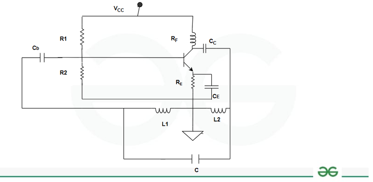
Hartley Oscillator Basic Design
The transistor and other parts must be powered by an appropriate power source. By connecting capacitors, the oscillator’s output signal can be retrieved.
- RF – Radio frequency coil used to give the VCC to collector side smoothly.
- Cb and Cc are the coupling capacitor at the base and the collector respectively that allows AC to pass and blocks the DC.
- RE is used for thermal stability.
- CE is the bypass capacitor; it prevents the bypassing through RE which results in large voltage drop across it and affects the oscillations of the output.
- L1 and L2 in series and parallel with C.
- Autotransformers can be used in case of inductors.
Working of Hartley Oscillator
- Capacitor C starts charging, when the supply is given.
- The capacitor starts discharging, once it is fully charged and the charge stored in the form of electrostatic field energy flows to inductor L2 where it is stored in the form of magnetic field.
- There will be no current flow to L2, (when the charger is fully discharged) which decreases current value in L2. Due to this there is decrease in magnetic field strength which results in the vanishing of magnetic field inside the inductor. This variation induces an emf i.e. back emf.
- Due to this back emf the capacitor starts charging again and the magnetic field in L2 gets converted into electrostatic field again. This leads to the oscillations across L2. These oscillations (or distortions) and output are in phase.
- Therefore, oscillations from L2 are transferred to L1 but undergoes a phase shift of 180° (due to the ground provided between L1 and L2).
- This is given to the Bipolar junction transistor where phase shift or 180° again takes place (Thus total phase shift of 360°).
- Hence, the condition for an amplifier to work as an oscillator is satisfied in accordance with Barkhausen criteria.
Shunt-fed Hartley Oscillator
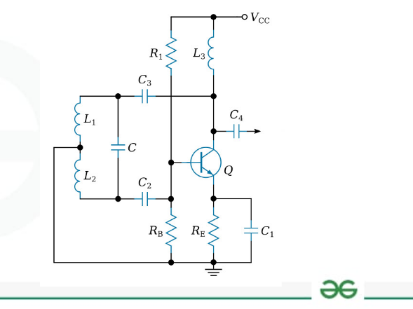
Shunt-fed Hartley Oscillator
A shunt-fed Hartley oscillator is a type of electronic oscillator circuit used to produce high-frequency signals. The circuit for the resonant LC tank is made up of an inductor (coil) connected in parallel to a capacitor. Usually, a capacitor is used to shift the inductor in order to produce feedback that allows oscillations to continue. The inductor and capacitor values determine the circuit’s resonant frequency, which is where self-sustaining oscillations occur when it is powered. Compared to other oscillator designs, the shunt-fed structure improves stability and frequency stability. shunt-supplied Because of their ease of use and effectiveness, Hartley oscillators are used in radio frequency (RF) circuits, signal generators, and communication systems.
Solved Examples on Hartley Oscillator
1. Derive the expression for frequency of Hartley Oscillator.
(From basic circuit diagram of Hartley Oscillator given above)
- R1, R2 and RE provides the necessary DC biasing to the transistor.
- Z1 and Z2 are the inductive reactance.
- Z3 capacitive Reactance.
Z1 = jωL1 + jωM and Z2 = jωL2 + jωM
Z3 = 1/ jωC = -j/ωC
Generalized equation of Oscillator: –
|
hie [ Z1 + Z2 + Z3] + Z1 Z2 (1 + hfe ) + Z1Z3 = 0
|
Substituting the values of Z1, Z2 and Z3 we get,
hie [jωL1 + jωM + jωL2 + jωM -j/ωC] + (jωL1 + jωM) (jωL2 + jωM) (1 + hfe ) + jωL1 + jωM -j/????C = 0
jω*hie [L1 + L2 + 2M – 1/ ω2 C] – ω2 [ L1 + M] [ L2 + M] [1 + hfe] + (L1 +M / C) = 0
To find ω (frequency) equate imaginary part = 0
hie /ω ( -1/C1 – 1/C2 + ω2 L) = 0
or ω2L = 1/C1 + 1/C2
ω = [1/L (1/C1 + 1/C2)]1/2
(ω = 2лf)
f = 1/ 2л [1/L (1/C1 + 1/C2)]1/2
2. Find the operating frequency of a Hartley Oscillator if L = 1mH and C1= 0.5mF and C2 = 0.2mF.
We know that operating frequency of a Hartley oscillator is given by the expression-
f = 1/ 2л [1/L (1/C1 + 1/C2)]1/2
∴ f = 1/ 2* 3.14 [ 1 / 1* 10-3 (1/ 0.5*10-3 + 1/0.2*10-3)
f = 1.146*106 Hz
Hartley Oscillator Using Op-Amp
Hartley Oscillator is constructed using op-amp, because it has many advantages over the Hartley Oscillator using BJT. The main advantage is the adjustment of output gain using the feedback resistors. The Hartley Oscillator constructed with BJT must have the output gain equal to or slightly greater than the ratio of L1/L2. Thus, it provides greater frequency stability to the output with lower output oscillations. Its working is same as that of BJT Hartley oscillator.

Basic Hartley Oscillator circuit using op-amp
The frequency of oscillation of this type of oscillator is given as:
f = 1/ 2π (Leq C); Where Leq = L1 + L2 + 2M OR L1 + L2
The gain of the above Hartley Oscillator is given as:
Av = (L1 + M)/ (L2 + M) where M is the mutual inductance of the coils
Conclusion
A traditional LC oscillator circuit that produces sinusoidal waves at a particular frequency with simplicity, stability, and efficiency is the Hartley oscillator. It enables radio frequency applications by using an inductor and capacitor combination, frequently in a feedback loop with a transistor or operational amplifier. It can be tuned across a range of frequencies due to its versatile architecture, which makes it suitable for a variety of signal production activities and communication systems. The Hartley oscillator is still a mainstay in electronic engineering despite its simple design. It offers dependable oscillation with few components, which makes it the go-to option for many applications that need accurate frequency generation.
FAQs on Hartley Oscillator
How to tune a Hartley oscillator?
To tune a Hartley oscillator to the desired oscillation frequency, the LC tank circuit’s capacitance or inductance must be adjusted. This can be accomplished by employing variable capacitors or inductors or by physically altering the component quantities.
What are the factors which influence the performance of a Hartley Oscillator?
Numerous factors can impact the stability and function of a Hartley oscillator. The external temperature and the components’ quality and uniformity are important factors. Changes in temperature or time can cause electronic components to naturally drift in value, which can alter the frequency of the oscillator. Therefore, low temperature coefficient components are frequently used in high precision applications.
What are the advantages of Colpitts Oscillators over Hartley Oscillators?
The Colpitts oscillator has a few major advantages over the Hartley oscillator, including a simpler construction and fewer components, which can facilitate design, reduce costs, and possibly improve dependability. Colpitts oscillators can also attain a greater tuning range and frequently show higher frequency stability, which makes them useful for a variety of applications, particularly in high-frequency circuits.
Share your thoughts in the comments
Please Login to comment...