In this article, we will go through the Wien Bridge Oscillator, first, we will start our article with the introduction of the bridge oscillator frequency, then we will go through the RC phase shift network and oscillator output gain and phase shift, then we will see Wien bridge oscillator frequency, then we will go through RC network and construction of bridge oscillator frequency using IC 741 operational amplifier, at last, we will conclude our article with solved examples, advantages, disadvantages and some FAQs.
What is Oscillator?
An oscillator in an Electronic Circuit that produces a repeated electronic signal, generally a sine wave, square wave or triangle wave. Oscillators convert Direct Current signals to Alternating Current signals which can be utilized to set frequency. Oscillators are used for audio applications, and utilized as a clock signal.
.webp)
Oscillator
Types of Oscillators
Different types of oscillators are:
- Wien Bridge Oscillator
- RC Phase shift Oscillator
- Colpitts Oscillator
- Hartley Oscillator
- Crystal Oscillator
- Phase Shift Oscillator
Here we are discussing about Wien Bridge Oscillator. It is one of the sine wave oscillators that uses an Resistor and Capacitance network to produce a sinusoidal waveform in output. The main component of this Oscillator Includes a network of resistors and capacitors along with an amplifier.
Wien Bridge Oscillator
Wien Bridge Oscillator is a phase shift Oscillator that generates sine wave. It is a two-stage Resistor Capacitor coupled amplifier circuit. It has good stability at its resonant frequency, low distortion and is exceptionally simple to tune but the phase shift of the output signal is not same as RC phase shift Oscillator.
In the Wien Bridge Network shown below, one branch has resistor(R1) and capacitor (C1 ) components are connected in series and the other branch has the Resistor (R2 ) and Capacitor (C2 ) are in parallel along with the resistors R3 and R4.
.webp)
Wien Bridge Network
Here resistors and capacitors are used to find the Impedance. For a series connection of R1 and C1 , Impedance is,
[Tex]Z_S = R_1 +X_{C_1}[/Tex]
For a parallel connection of R2 and C2 the Impedance is,
[Tex]Z_{P}=R_{2}|| X_{C_{2}}[/Tex]
RC Phase Shift Network
RC Phase shift Oscillator produces a sine wave as output signal using regenerative feedback attained from the combination of resistor and capacitor. As Capacitors are used to store an electric charge, Forms the Renewing feedback in the RC network.

RC Phase shift Oscillator using Operational Amplifier
Oscillations only occur at the frequency in which the overall phase-shift is 360°.This resistor-capacitor feedback network can be connected to produce a leading phase shift or switched to produce a phase shift delay and the result is still the same as the sine wave. By changing one or more of the resistors or capacitors in the phase-shift network, the frequency can be varied.
Oscillator Output Gain and Phase Shift
At high frequencies circuit behaves like lag circuit and the reactance of the parallel capacitor, (C2) turns out to be exceptionally low, so this capacitor acts like a short circuit across the output, so there is no output signal.
At low frequencies circuit behaves like lead circuit and the reactance of the series capacitor (C1) becomes exceptionally high , it act as an open circuit, blocking the input signal produces no output signal.
The frequency of the input waveform at which output voltage reaches its maximum value (in between C1 being open-circuited and C2 being short-circuited ) is called the Resonant Frequency.
At resonant frequency, the circuit’s reactance( XC) equals to its resistance( Xc = R), and the phase difference between the input and output equals zero degrees (0°).
The magnitude of the output voltage at its maximum is equal 3 or more times of the input voltage which is taken as Voltage gain (AV ).
[Tex] V_{out } \geq 3 V_{in}[/Tex]
[Tex]\frac{V_{out}}{V_{in}}\geq 3[/Tex]
[Tex]A_{v}\geq 3[/Tex]
Wien Bridge Oscillator Frequency
The Wien Bridge Oscillator frequency at resonance is,
[Tex]f_{r}=\frac{1}{2\pi RC}[/Tex]
Where fr = Resonant Frequency in Hertz
C = Capacitance in Farads
R = Resistance in Ohms
The total phase shift of the Wien Bridge oscillator circuit is 0° at resonance(Circuit is balanced). The frequency of oscillation is equal to the resonant frequency of the circuit.
The RC Network
Consider the RC network consist of resistors and capacitors as shown below,

RC Network
It consists of two Resistor – Capacitance circuits connected together and the output is taken across these circuits. Resistor and capacitor (R1 and C1 ) forms the series RC Circuit and the resistor and capacitor(R2 and C2 ) forms the parallel RC circuit.
The total impedance of the Resistor R1 and Capacitor C1 together called as ZS or termed as series Impedance and the total impedance of the Resistor R2 and Capacitor C2 together called as ZP or termed as Parallel Impedance. As ZS and ZP are connected together in series across the input, Vin structures a voltage divider network with the result taken from these circuits as shown above.
Series Circuit
The series RC circuit is shown below,

Series RC Circuit
The total impedance of the series combination with resistor (R1) and capacitor (C1) is,
Take, R1 = R2 =R, C1 = C2 = C,
Consider,
Series Impedance is,
ZS= R+ XC
Parallel Circuit
The parallel RC circuit is shown below,

Parallel RC Circuit
The total impedance of the lower parallel combination with resistor, R2 and capacitor, C2 is given as:
[Tex]\frac{1}{Z_{p}}=\frac{1}{R}+\frac{1}{X_C}
[/Tex]
[Tex]\frac{1}{Z_{p}}=\frac{R+X_{C}}{RX_{C}}[/Tex]
[Tex]Z_{p}=\frac{RX_{C}}{R+X_{C}}[/Tex]
Use voltage divider rule,
[Tex]\frac{V_{in}}{V{out}}=\frac{Z_{P}}{Z_{P}+Z_{S}}[/Tex]
[Tex]\frac{V_{in}}{V{out}}=\frac{\frac{RX_{C}}{R+X_{C}}}{\frac{RX_{C}}{R+X_{C}}+R+X_C}[/Tex]
[Tex]\frac{V_{in}}{V{out}}=\frac{RX_{C}}{RX_{C}+(R+X_{C})^{2}}[/Tex]
[Tex]\frac{V_{in}}{V{out}}=\frac{RX_{C}}{RX_{C}+R^{2}+(X_{C})^{2}+2RX_C}[/Tex]
[Tex]\frac{V_{in}}{V{out}}=\frac{RX_{C}}{R^{2}+(X_{C})^{2}+3RX_C}[/Tex]
We know that feedback gain (β ) is,
[Tex]\beta=\frac{V_{in}}{V{out}}=\frac{RX_{C}}{R^{2}+(X_{C})^{2}+3RX_C}[/Tex]
We also know that Voltage gain (Av),
[Tex]A_v=\frac{V_{out}}{V{in}}=1+\frac{R_{3}}{R_4}[/Tex]
Use the formula,
[Tex]A_v \beta =1[/Tex]
Substitute the values,
[Tex](1+\frac{R_3}{R_4})\frac{RX_{C}}{R^{2}+(X_{C})^{2}+3RX_C}=1[/Tex]
Use [Tex]X_C=\frac{1}{j \omega C}[/Tex]
[Tex](1+\frac{R_3}{R_4})\frac{\frac{R}{j \omega C}}{R^{2}+(\frac{1}{j \omega C})^{2}+3R\frac{1}{j \omega C}}=1[/Tex]
[Tex](1+\frac{R_3}{R_4})\frac{R}{j \omega C}=R^{2}+(\frac{1}{j \omega C})^{2}+3R\frac{1}{j \omega C}[/Tex]
[Tex](1+\frac{R_3}{R_4})R={j \omega C}\times[ R^{2}+(\frac{1}{j \omega C})^{2}+3R\frac{1}{j \omega C}][/Tex]
[Tex](1+\frac{R_3}{R_4})R={j \omega C} R^{2}+(\frac{1}{j \omega C})+3R[/Tex]
[Tex](1+\frac{R_3}{R_4})j\omega CR=({j \omega C})^{2} R^{2}+1+3R j\omega C[/Tex]
[Tex](1+\frac{R_3}{R_4})j\omega CR-3Rj \omega C=(j^{2} (\omega)^{2} C)^{2} R^{2}+1[/Tex]
Use j2 = -1,
[Tex]j\omega[(1+\frac{R_3}{R_4})RC-3RC]=1- \omega^{2} c^{2} R^{2}[/Tex]
To get the oscillation frequency Take real part is equal to zero,
[Tex]1- \omega^{2} C^{2} R^{2}=0[/Tex]
[Tex]1= \omega^{2} C^{2} R^{2}[/Tex]
[Tex]\omega^{2} =\frac{1}{C^{2} R^{2}}[/Tex]
[Tex]\omega =\frac{1}{ RC}[/Tex]
We, know [Tex]\omega = 2\pi f[/Tex]
[Tex]2\pi f=\frac{1}{ RC}[/Tex]
[Tex] f=\frac{1}{2\pi RC}[/Tex]
Construction of Wien Bridge Oscillator using IC 741 Operational Amplifier
The Operational-Amplifier is required to function as a non-inverting amplifier in the Wien-Bridge network as the Wien bridge circuit provides zero phase-shift. From the circuit, it is clear that the output voltage is given back to both inverting and non-inverting input terminals. At resonant frequency, the voltages applied to the inverting will be equal and voltages applied to the non-inverting terminals will be in-phase with each other. Due to the Restriction by the open-loop gain , These kind of Operational-Amplifier-based Wien Bridge Oscillators cannot operate above 1 MHz . The voltage gain of the amplifier needs to be more than 3 to start oscillations and equal to 3 to sustain them i.e (Av≥ 3).
The circuit below shows the Wien Bridge Oscillator using IC 741 operational amplifier. It has Resistor R1 and Capacitor C1 are in series connected to Non inverting terminal of IC 741 at terminal (3), similarly Resistor R2 and Capacitor C2 are in parallel connected to Non inverting terminal of IC 741 at terminal (3). Here Resistor R3 is a variable Resistor which is connected to Inverting terminal at terminal (2) and output of op- amp at terminal (6). Direct Current power Supplies of +12V is connected to terminal (7) and -12V is connected to terminal (4).
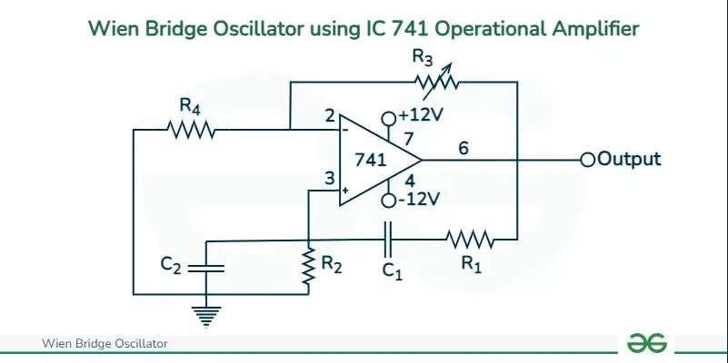
Wien Bridge Oscillator using IC 741 Operational Amplifier
At low frequencies, the reactance of the capacitors C1 and C2 will become very high and the output voltage V0 will remain at zero and called as ‘lag circuit’, as the capacitor C1 will act as an open circuit. In this circuit, at high frequencies, the reactance of the capacitors C1 and C2 will be much less due to which the Output voltage V0 will become zero then the Resistor R2 will be shorted due to the capacitor C2 and called as ‘lead circuit’.
As there is a lead-lag circuit, the circuit doesn’t provide any phase shift at Oscillating frequency, So non-inverting Amplifier is used.
As op-amp is operated in the non-inverting configuration the voltage gain is shown below,
[Tex]\frac{V_{out}}{V_{in}}=1+\frac{R_{3}}{R_{4}}=3[/Tex]
Solved Examples on Wien Bridge Oscillator
A Wien Bridge Oscillator circuit is required to generate a sinusoidal waveform of 3,200 Hertz (3.2kHz). Calculate the frequency and determine the resistors R1 and R2 and the capacitors C1 and C2.
Given fr = 3.2 kHz
If resistors R1 = R2 and capacitors C1 = C2 and Assume a value for the feedback capacitors of 3.8nF, then the corresponding value of the feedback resistors is calculated,
We know,
[Tex]f_{r}=\frac{1}{2\pi RC}[/Tex]
Here C= 3.8nF, fr = 3.2 kHz,
[Tex]3.2\times 10^{3}=\frac{1}{2 \pi \times R \times 3.8\times 10^{-9}}
[/Tex]
R = 13088 Ω (or) 13.1 kΩ
To get the sinusoidal wave the voltage gain of the Wien bridge Oscillator is greater than or equal to 3,
[Tex]A_{V} \geq 3[/Tex]
[Tex]\frac{V_{out}}{V_{in}}\geq 3[/Tex]
[Tex]1+\frac{R_{3}}{R_4}\geq 3[/Tex]
Take,
[Tex]1+\frac{R_3}{R_4}=3[/Tex]
[Tex]\frac{R_3}{R_4}=3-1[/Tex]
[Tex]\frac{R_3}{R_4}=2[/Tex]
[Tex]R_4=\frac{1}{2}R_3[/Tex]
If R3 = 80 kΩ, then R4 = 40 kΩ.
In the Wien Bridge oscillator, R1 = R2 = 200k Ohms and C1 = C2 = 600 pico Farads. Find the oscillating frequency of the circuit.
Given,
Resistance is,
[Tex] R= R_1 = R_2 = 200\text{k Ohms} = 200 \times 10^{3}[/Tex]
Capacitance,
[Tex]C=C_1 = C_2 = 600 \ \text{pico Farads}=600\times 10^{-12}=6\times 10^{2}\times 10^{-12}=6\times 10^{-10}[/Tex]
To find the frequency, use the formula,
[Tex]f=\frac{1}{2\pi RC}[/Tex]
Substitute R,C values in f,
[Tex]f=\frac{1}{2\pi \times 200\times 10^{3}\times 6 \times 10^{-10}}[/Tex]
f=1326 Hz
The frequency of oscillation is, 1326 Hz (or) 1.326 kHz
Difference Between Wien Bridge Oscillator and RC Phase Shift Oscillator
RC Phase shift Oscillator
| Wien Bridge Oscillator
|
|---|
The total phase shift for positive feedback (0° or 360°)
| The phase shift of the Wien Bridge oscillator is 0°.
|
Operational-amplifier is used in inverting mode
| Operational-amplifier is used in non-inverting mode.
|
Amplifier gain of the RC Phase shift Oscillator is, |A| >=29
| Amplifier gain of Wien Bridge Oscillator is, |A| >= 3
|
The Frequency of oscillation is,
[Tex]f_{0}=\frac{1}{2\pi RC \sqrt{6}}[/Tex]
| The Frequency of oscillation is,
[Tex]f_{0}=\frac{1}{2\pi RC}[/Tex]
|
Difficult to adjust frequency.
| Easy to adjust frequency by varying the capacitors.
|
Advantages of Wien Bridge Oscillator
- Stability: The Stability of the Wien Bridge Oscillator circuit is high.
- Output: It produces Constant output
- Distortion: It produces low distortion and is very easy to tune.
- Frequency: The frequency of oscillation is easily varied by adjusting the Resistance and Capacitance network.
- Design: Very simple design structure and works easily.
Disadvantages of Wien Bridge Oscillator
- Amplitude: It has Low output amplitude.
- Dependency: Dependency on gain adjustment for oscillation frequency.
- Range: Inability to produce high frequencies, so operated up to particular maximum frequency.
- Distortion: It can cause high output distortion.
- Complex: It requires large number of circuit components.
Applications of Wien Bridge Oscillator
- Stable Oscillations: Wien bridge oscillators are used in scientific research experiments for generating stable oscillations in various physical and chemical measurements, frequency response analysis.
- Modulation- Demodulation circuits: Wien bridge oscillators are used in communication systems for generating carrier signals, clock signals in transmitters, receivers, and modulation-demodulation circuits.
- Frequency: The Wien bridge oscillator is used in digital frequency meters for measuring the frequency of signals accurately.
- Used for signal processing in communication devices.
Conclusion
Wien Bridge Oscillator is a simple but powerful electronic circuit, It has the ability of generating nearly sinusoidal waveforms over a wide range of frequencies. Due to it’s advantages like ease of tunability, simple design and the purity of its output have made it usable in electronic engineering and other related fields.
Despite its few disadvantages, its influence in modern electronics is undeniable, marking its importance not just historically but also in modern applications. Understanding its design and operation provides a beginning for the study and development of complex wave-generating circuits in today’s digital world using its advantages. The frequency ranging from 1Hz to 1MHz.
Wien Bridge Oscillator – FAQs
At the resonant frequency, what is the phase shift for the output in a Wien Bridge oscillator?
At resonant frequency the phase shift for the output in a Wien Bridge oscillator 0°, because this Oscillator uses a feedback circuit which consists of a series RC circuit connected to a parallel RC network, producing a phase delay or phase advance circuit depending on the frequency.
What are conditions for Sustained Oscillations in a Wien Bridge Oscillator?
The necessary Conditions for sustained oscillations are,
The Voltage gain required is given by [Tex]AV \geq 3[/Tex]
For a Wien Bridge Oscillator circuit using Op-Amp,
[Tex] 1+\frac{R_4}{R_3} = 3[/Tex]
Then,
[Tex]R_4 = \frac{1}{2}R_3[/Tex] is the relation required.
Given that R1=10kΩ, C1=1nF, R2=10kΩ, C2=1nF, find the approximate resonant frequency for a Wien Bridge Oscillator Circuit?
Use the resonant frequency formula for a Wien Bridge Oscillator,
[Tex]f_{r}=\frac{1}{2\pi RC}[/Tex]
Here R1 =R2 = R, C1=C2 =C
[Tex]f_{r}=\frac{1}{2\pi\times 10\times 10^{3}\times 1\times 10^{-9}}[/Tex]
fr = 15915 Hz (or) fr = 15.9 kHz
Share your thoughts in the comments
Please Login to comment...