Designing methods of hardwired control unit
Last Updated :
26 May, 2021
Prerequisites : Hardwired control unit
Here the control signals are generated using hardware.
There are three types of Hardwired Control Units.
1. State table method :
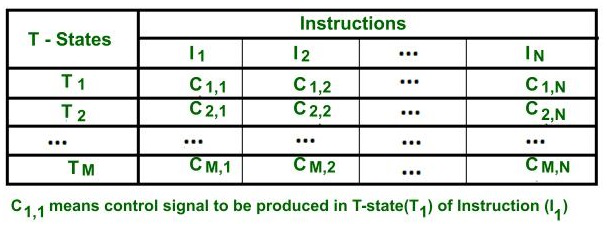
State table method
- Here the behavior of control unit is represented in the form of a table, which is known as the state table.
- Here, each row represents the T-states and the columns represent the instructions.
- Every intersection of the specific column to each row indicates which control signal will be produced in the corresponding T- state of an instruction.
- Here the hardware circuitry is designed for each column(i.e. for a specific instruction) for producing control signals in different T-states.
Advantage –
- It is the simplest method.
- This method is mainly used for small instruction set processors(i.e. in RISC processors).
Drawback –
- In modern processors ,there is a very large number of instruction set. Therefore, the circuit becomes complicated to design, difficult to debug, and if we make any modifications to the state table then the large parts of the circuit need to be changed.
- Therefore ,this is not widely used for these kinds of processors.
- There are many redundancies in circuit design like the control signals are required for fetching the instruction is common and which is repeated for N number of instruction. So the cost of circuitry design may increase.
2. Delay element method :
- Here the control unit behavior is represented in the form of a flowchart.
- Each step in the flowchart represents a control signal that needs to be produced for processing the instructions.
- If all the steps of the instructions are performed, this means the instruction is executed completely.
- Control signals perform micro-operations and each micro-operation requires one T-state.
- For the micro-operations which are independent, they are required to be performed in different T-state. Therefore, for every consecutive control signal an exactly 1-state delay is required, which can be produced with the help of D FF.
- Therefore. D Flip-Flops are inserted between every two consecutive control signals.
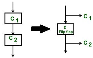
- As we can observe, the D FF is introduced between each pair of control signals .Therefore, after a control signal is generated, then the delay element before that control signal is not in use until before the next instruction required that control signal. Therefore, of all D Flip-Flops, only one will be active at a time. Therefore, this method is also known as one hot method.
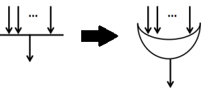
- In a flowchart, if there is a multiple entry point for control signal then to combine two or more paths, we use an OR gate.
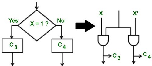
- A decision box is converted into a set of two complementing AND gates.
Example –
Suppose the processor has two instructions add or subtract (Therefore an opcode of 1 bit is needed in which 0 opcode for add instruction and 1 for subtract is used.
Delay element method for generating control signals.
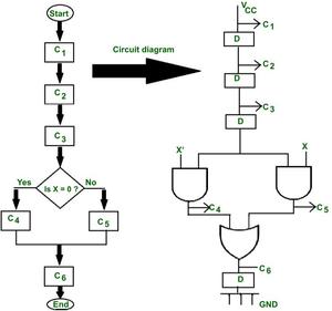
Flowchart design –
Say C1,C2,C3 is the control signals for fetching the instruction. When X= 0, then C4 control signal is produced (i.e. decoding) which is used for performing add operation, and when x=1, then control signal C5 will be produced for performing the subtract operation. And c6 control signal is used for storing the result and the process ends.
Circuit design –
Between two consecutive control signals which are independent, one delay element is introduced between them to produce a delay of 1 T state. The decision box is converted into and complemented AND gate circuit(i.e. if x= 0 then x’= 1, so, a c4 control signal is generated.
Advantage –
- This method has a logical approach ,therefore it helps to reduce the circuit complexity.
- For the common control signals which need to be generated in every instruction, for them only one circuitry can be designed .
Drawback –
- As the number of instructions increases , the number of D FF for generating delay is increased, so overall circuit complexity and cost increases.
3. Sequence counter method :
Sequence Counter method
- This is the most popular and most commonly used method for generating delays between every consecutive control signal.
It’s main advantage is that it uses the logical approach of flowchart and doesn’t use the unnecessary number of D FF.
- First, a flowchart is designed to represent the behavior of a control unit.
- It is then converted into a circuit using the same method of AND & OR gates (as seen above in the Delay element method).
Example of 2 instructions used in the delay element method
Example of 2 instructions used in the delay element method[/caption]
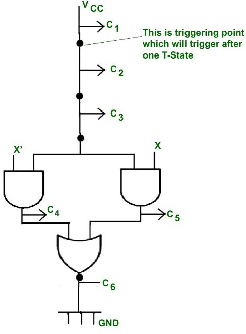
- It is similar to the delay element method, but the only difference is that instead of unnecessary D Flip flops there are triggering points in the circuit. They are activated after a gap of one-one T-state.
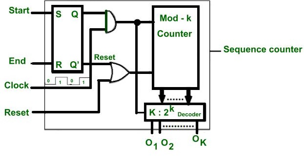
Working of Sequence counter circuit –
- Here one SR FF , one decode and one counter is used.
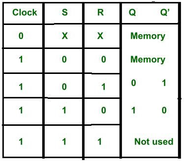
Truth table of SR FF
- When the instruction cycle starts, then start = 1.
- As we know, when Start = 1, because S is connected to Start, therefore Q becomes 1 and and Q’ becomes 0.
- Here the level triggering clock is used. Therefore, when clock = 1 or high and Start=1, as both outputs are connected to AND gate, so if the resultant of both is 1 that will enable the counter and counter starts counting from 0 0 0 state. So the 0 0 0 state is decoded by a decoder and produces output O1 , which will trigger the triggering point in the control circuit.
- As the clock becomes high again after 1 T-state. Therefore, when clock = 0, then the counter state is preserved(Q and Q’) remains the same until the clock becomes high again. This makes sure that the counter changes its states after a gap of one-one T state.
- Suppose the counter is 3 bits, it generates 23 = 8 states(000 001 ….. 111) . The first count 0 0 0 is given to 3:8 decoder. It will active output number 1. This output is not a control signal but this will trigger the triggering point in the control unit circuit.
- As the clock becomes high again after a gap of one T state, therefore clock =1 and start = 1 ,then the counter is enabled and changes it state to 001 and the counter decodes the count and makes O2 output high . And this will trigger a second triggering point in the circuit.
- All counting states are decoded in the same manner.
If the counter is of K bits then K:2K decoder is required this can produce 2K outputs and that will trigger the 2K triggering points after a gap of 1-1 T-states in the circuit.
- When the instruction ends, the control signal is generated to make End pin = 1, and the counter is reset, so the next time, it begins from the first count(0 0 0 ).
- If reset pin =1, then the counter will reset and after that it will again start counting from 000 states.
Advantages :
- Less number of flip-flops are used.
Disadvantages of hardwired control unit :
- In modern processors ,there is a very large number of instruction set. Therefore, the circuit becomes complicated to design, difficult to debug, and if we make any modifications then a large part of the circuit needs to be changed. Therefore, it is suited for RISC processors.
Share your thoughts in the comments
Please Login to comment...