Connection Between Star and Mesh Topology in Cisco
Last Updated :
26 Apr, 2024
A local Area Network (LAN) is a data communication network connecting various terminals or computers within a building or limited geographical area. In this article, we will know about how to implement a topologies connection between 2 LAN/Topologies in Cisco Packet Tracer.
Steps to Configure and Verify Connection between Two LANs in Cisco Packet Tracer:
Step 1: First, open the Cisco packet tracer desktop and select the devices given below:
| S.NO |
Device |
Model Name |
Qty. |
| 1. |
PC |
PC |
8 |
| 2. |
Switch |
2496-24TT, PT-Switch |
5 |
| 3. |
Router |
2911 |
1 |
IP Addressing Table for PCs of LAN1 and LAN2:
LAN1-
| S.NO |
Device |
IPv4 Address |
Subnet Mask |
Default Gateway |
| 1. |
PC0 |
13.12.11.1 |
255.0.0.0 |
13.12.11.5 |
| 2. |
PC1 |
13.12.11.2 |
255.0.0.0 |
13.12.11.5 |
| 3. |
PC2 |
13.12.11.3 |
255.0.0.0 |
13.12.11.5 |
| 4. |
PC3 |
13.12.11.4 |
255.0.0.0 |
13.12.11.5 |
LAN2-
| S.NO |
Device |
IPv4 Address |
Subnet Mask |
Default Gateway |
| 1. |
PC4 |
192.168.1.1 |
255.255.255.0 |
192.168.1.5 |
| 2. |
PC5 |
192.168.1.2 |
255.255.255.0 |
192.168.1.5 |
| 3. |
PC6 |
192.168.1.3 |
255.255.255.0 |
192.168.1.5 |
| 4. |
PC7 |
192.168.1.4 |
255.255.255.0 |
192.168.1.5 |
- Then, create two network topologies (Ring and Bus)as shown below the image.
- Use an Automatic connecting cable to connect the devices with others.
Representation of the topologies should look like the image given below:
Step 2: Configure the PCs (hosts) with IPv4 address, Subnet Mask, and Default gateway according to the IP addressing table above.
- To assign an IP address in PC0, click on PC0.
- Then, go to desktop and IP configuration and there you will find IPv4 configuration.
- ‘Fill IPv4 address, subnet mask, and default gateway to the particular input box.
- Repeat the same procedure with PCs of LAN2 to configure them.
Step 3. Assigning IP address using the ipconfig command.
- We can also assign an IP address with the help of a command.
- Go to the command terminal of the PC0.
- Then, type iPConfig <IPv4 address><subnet mask><default gateway>(if needed)
Example: ipconfig 13.12.11.1 255.255.255.0 13.12.11.5
- Repeat the same procedure with other PCs of Both LANs to configure them thoroughly.
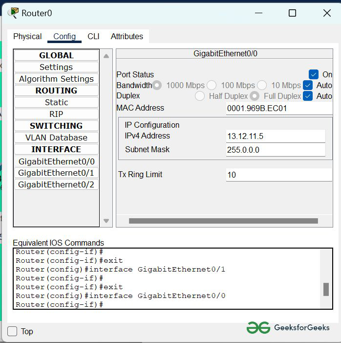
Step 4: Configure router with IP address and Subnet mask.
IP Addressing Table Router:
| Device |
Interface |
IPv4 Address |
Subnet mask |
| Router0 |
FastEthernet0/0 |
13.12.11.5 |
255.255.255.0 |
| FastEthernet0/1 |
192.168.1.5 |
255.255.255.0 |
- To assign an IP address in router0, click on router0.
- Then, go to config and then Interfaces.
- Then, configure the IP address in Fast Ethernet and serial ports according to IP addressing Table.
- Fill IPv4 address and subnet mask.
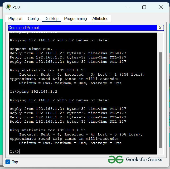
Step 5: Verifying the network by pinging the IP address of any PC. We will use the ping command to do so.
- First, click on PC0 then Go to the command prompt
- Then type ping <IP address of targeted node>
- As we can see in the below image we are getting replies which means the connection is working properly.
Example : ping 192.168.1.2
Simulation Result:
Share your thoughts in the comments
Please Login to comment...