Synchronous Series Carry Counter
Last Updated :
23 Apr, 2020
Synchronous Series Carry Counter is such a synchronous counter where inputs of flip-flops are connected in such a manner that only those flip-flops that are toggle on a given clock will have input value as the logic 1. The advantage of this counter is that it reduces the decoding error.
Block Diagram of Synchronous Series Carry Counter:
Here is the block diagram of a 4-bit (MOD-16) series carry counter.
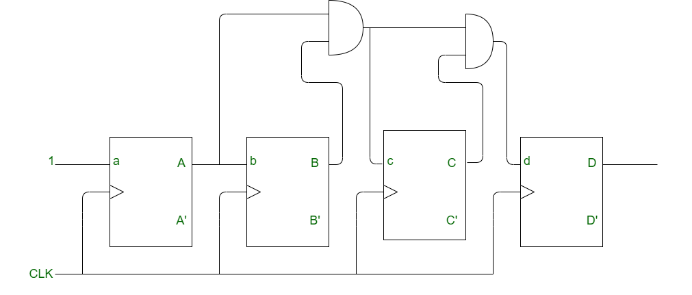
In the above counter:
- A toggles for every CLK pulse is applied.
- B toggles when A = 1 and CLK pulse is applied.
- C toggles when B = 1 and A = 1 and CLK pulse is applied.
- D toggles when C = B = A = 1 and CLK pulse is applied.
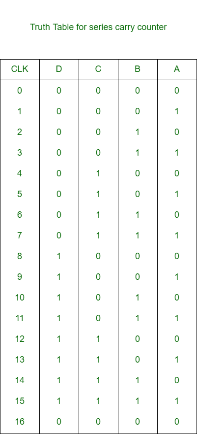
Truth Table for Series Carry Counter:
Note:
In order to get the synchronous down counter, complemented output (A’, B’ etc.) of each stage is connected to the input of the next stage.
Total Time Delay :
The total delay for synchronous series carry counter is:
T >= t(pd) + (n-2) x t(pd of AND gate)
As the number of bit increases, the propagation delay of flip-flops and the propagation delay of AND gate also increases, this will increase the total delay of the circuit.
Advantage of Series Carry Counter:
Most important advantage of the series carry counter is that it reduces the decoding error.
Share your thoughts in the comments
Please Login to comment...