Synchronous Parallel-Carry Binary Counter
Last Updated :
29 Apr, 2021
Synchronous Counter: It is a digital circuit that performs counting in binary numbers with the help of flip-flops and all flip-flops triggered simultaneously.
Synchronous Counter design procedure for a given counting sequence:
- Identify the numbers of flip-flops(FFs), inputs, and outputs required for the count sequence.
- Select the type of FF going to use.
- Construct the state table containing current state and next state of the counter and the excitation table of FFs used.
- Find the equations or expressions for each input of FFs. Here we can use K-map method which provides minimized expression.
- Now make connections among FFs and gates used according to expressions obtained in step 4.
Example– First, we will implement a 4-bit synchronous up counter using T-FF. So, we need 4 FFs, which are FF0, FF1, FF2, and FF3. It can count from 0 to 15(16 numbers). Following is the table for this counter using excitation table for T-FF,
|
Current state
|
Next state
|
Input to FFs
|
| Q3 |
Q2 |
Q1 |
Q0 |
Q3 |
Q2 |
Q1 |
Q0 |
T3 |
T2 |
T1 |
T0 |
| 0 |
0 |
0 |
0 |
0 |
0 |
0 |
1 |
0 |
0 |
0 |
1 |
| 0 |
0 |
0 |
1 |
0 |
0 |
1 |
0 |
0 |
0 |
1 |
1 |
| 0 |
0 |
1 |
0 |
0 |
0 |
1 |
1 |
0 |
0 |
0 |
1 |
| 0 |
0 |
1 |
1 |
0 |
1 |
0 |
0 |
0 |
1 |
1 |
1 |
| 0 |
1 |
0 |
0 |
0 |
1 |
0 |
1 |
0 |
0 |
0 |
1 |
| 0 |
1 |
0 |
1 |
0 |
1 |
1 |
0 |
0 |
0 |
1 |
1 |
| 0 |
1 |
1 |
0 |
0 |
1 |
1 |
1 |
0 |
0 |
0 |
1 |
| 0 |
1 |
1 |
1 |
1 |
0 |
0 |
0 |
1 |
1 |
1 |
1 |
| 1 |
0 |
0 |
0 |
1 |
0 |
0 |
1 |
0 |
0 |
0 |
1 |
| 1 |
0 |
0 |
1 |
1 |
0 |
1 |
0 |
0 |
0 |
1 |
1 |
| 1 |
0 |
1 |
0 |
1 |
0 |
1 |
1 |
0 |
0 |
0 |
1 |
| 1 |
0 |
1 |
1 |
1 |
1 |
0 |
0 |
0 |
1 |
1 |
1 |
| 1 |
1 |
0 |
0 |
1 |
1 |
0 |
1 |
0 |
0 |
0 |
1 |
| 1 |
1 |
0 |
1 |
1 |
1 |
1 |
0 |
0 |
0 |
1 |
1 |
| 1 |
1 |
1 |
0 |
1 |
1 |
1 |
1 |
0 |
0 |
0 |
1 |
| 1 |
1 |
1 |
1 |
0 |
0 |
0 |
0 |
1 |
1 |
1 |
1 |
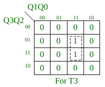
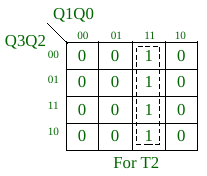
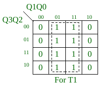
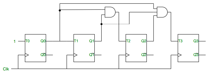
Using K-map, we can find boolean expressions for T0, T1, T2, and T3.
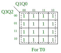
So, T0 = 1,
T1 = Q0,
T2 = Q0.Q1,
T3 = Q0.Q1.Q2,
4-bit Synchronous Series-Carry Up Counter: For the above example, we can use this link(article) to implement series-carry counter. And in this series-carry counter, fan-in value(number of inputs) for all used AND gates is 2, and it is fixed.
Why do we need synchronous parallel-carry counter over synchronous series-carry counter? If we see the implementation of series-carry counter for the above example, its AND gates use the outputs of some other AND gates. As in the above-obtained expression, the AND gate which produces Q0.Q1.Q2 can use the output of AND gate that produces Q0.Q1, or we can write T3 = T2.Q2. The same can be applied to higher count sequences. This arrangement can lead to the increment of the level of the circuit of counter. And high level means more time required for a stable state of the circuit. Same thing we can see in the above link that the delay of one increment in count is dependent on the number of FFs. So, we use the synchronous parallel-carry counter which reduces the level of the circuit.
4-bit Synchronous Parallel-Carry Up Counter:
For above given example
Logic diagram-
Timing diagram-
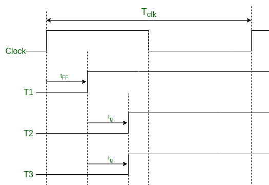
Here,
Tclk >= tff + tg , n>=3 ………………. (a)
where
- Tclk — time period of clock used.
- tff — time required for a FF to complete its operation.
- tg — the maximum time required for any gate to complete its operation.
- n — number of FFs used.
Idea behind parallel-carry counter– In this design, we try to implement a circuit with 2-level only. The first level reserved for FFs and the second level is for the execution of gates used in the circuit. Whatever is the count sequence, parallel-carry counter always remains in a 2-level circuit, but the series-carry counter increases the level as counting numbers increases. We can say Synchronous Parallel-Carry Counters are much faster than Synchronous Series-Carry Counters.
Advantage: In equation (a), the time period is independent of the number of FFs or counting numbers(if n>=3). So, whatever the size of the counting sequence the time period of the clock will remain the same. But, this is not possible in the case of series-carry counter. This is a major advantage of the synchronous parallel-carry counter over the synchronous series-carry counter.
Disadvantage: Fan-in value(number of input) for AND gates used in the counter increases linearly with the number of FFs. For n number of FFs in counter we need AND gates with fan-in value from 2 to n-1. And a gate with a much higher fan-in value practically not exist. So, for less count sequence size parallel-carry counter is much better than series-carry counter, but not for a high count sequence size.
Some facts about synchronous parallel-carry and series-carry counters for the above example
- We can see that number of gates required in both counters are same for the same counting numbers.
- Above both counters used the AND gates, but the type of gates can be changed according to the count sequence. It totally depends on the minimized expression we obtained for all inputs of FFs in step 4 of the procedure. For example, Ring counter is a synchronous counter, but there is no use of any AND gate or other gates.
Strategy to minimize the disadvantages of both parallel-carry and series-carry counter
We can make a counter by combining the features of both of the above counters. For example, we can use the new gates that use some values of the other gates as in series-carry counter, but it has fewer fan-in values than the gate used corresponding to this in parallel-carry counter. For example, a counter with n FFs and n is higher, series-carry counter will have n-1 levels(1 for FFs and n-2 for gates) and parallel carry counter will have a 2-level circuit, now we can implement a circuit for a counter of level nearly n/2. This strategy applied for the count sequence of type as in given example.
Like Article
Suggest improvement
Share your thoughts in the comments
Please Login to comment...