An inverter is a fundamental electrical device designed primarily for the conversion of direct current into alternating current . This versatile device , also known as a variable frequency drive , plays a vital role in a wide range of applications , including variable frequency drives and high power scenarios such as high voltage direct current (HVDC) power transmission. Its primary function is to control the torque and speed of electrical motors , making a vital role in many industrial and commercial settings. The versatility of inverters extends to their role in HVDC power transmission, where they are crucial in converting the DC power generated in power plants or offshore wind farms into AC power suitable for long transmission .
In this context , inverters help minimize energy losses and maximize the efficiency of electricity distribution over extensive distances. Here we will discuss about circuit design and working of inverter , types of inverters , advantages , limitations and applications of inverters .
Three Phase Inverter
A three phase inverter is a device that converts dc source into three phase ac output . This conversion is achieved through a power semiconductor switching topology. in this topology , gate signals are applied at 60-degree intervals to the power switches , creating the required 3-phase AC signal. This type of inverter commonly employed in conjunction with photovoltaic(PV) modules or the grid . The fundamental principle behind its operation involves the use of three individual inverter switches , with each switch is dedicated to one of the three output phases. To generate a balanced and synchronized ac output waveform , these switches are precisely controlled. Each switch operates at specific intervals , ensuring that only one switch is active at every 60-degrees of the basic output waveform . In essence , a 3-phase inverter is a crucial component for efficiently converting DC power into 3-phase AC power needed for various applications, especially in renewable energy systems like solar PV installations and industrial setups where three phase power is essential for running machinery and equipment.
Types of Three Phase Inverter
Three phase inverters are classified many types according to their features and characteristics . Some of the inverters are:
- Voltage Source Inverter
- Current Source Inverter
- Cascaded Multilevel Inverter
- Hybrid Multilevel Inverter
- Pulse Width Modulated Inverter
Voltage Source Inverter
A voltage source inverter (VSI) is an inverter that converts DC source voltage into an AC output voltage. It is also known as voltage -fed inverter, suitable for situations where the DC source has negligible or low impedance. VSIs are commonly used in Variable-Frequency Drive(VFD) systems to control the speed of 3-phase motors. In this type of inverter DC voltage is very small i.e. negligible and having small impedance .Hence these inverters are also called as voltage fed inverters . These kind of inverters are only used for buck operation and these are used in three phase inverters where the power requirement is high. In VSIs, the DC voltage source is usually provided by battery banks ,consisting of multiple cells connected in series and parallel configurations. This model ensures a reliable and stable DC supply. In some cases, photovoltaic (PV) cells are used as the DC source, harnessing solar energy to power the inverter.
.png)
Voltage Source Inverter
Current Source Inverter
In current source inverter DC current source is converted into AC current at required frequency. In this type of inverters source current is always constant. Hence ,these inverters are called as current fed inverters. These are used only for boost operation and it is not possible to use with more than one motor. The output AC current ‘s frequency is determined by the switching frequencies of various semiconductor devices such as transistors and thyristors. Notably , the defining feature of this inverter is that the input current remains constant. A typical current source inverter setup consists of a DC current source, filters and on an AC load. These inverters are available in both single-phase and three-phase configurations, making them versatile for a wide range of applications. They find use in tasks like starting synchronous motors, power factor correction units, speed control of AC motors, induction heaters, plasma generators, uninterruptible power supplies(UPS),lagging Var compensators and more.
.png)
Current Source Inverter
Cascaded Multilevel Inverter
Cascaded Multilevel Inverter is a 3-phase inverter designed for electric utility applications, offering precise control by employing multiple voltage levels to create a stepped waveform. It typically comprises(M-1)/2 H-bridges, each supported by its DC capacitor. These inverters are crucial in renewable energy systems and high-voltage power transmission. By providing enhanced voltage quality and efficient power conversion, they are well- suited for application where stable AC power generation is essential, particularly in the integration of renewable energy sources like solar and wind, as well as in high-voltage transmission systems, ensuring reliable and controlled power delivery over long distances.

Cascaded Multilevel Inverter
Hybrid Multilevel Inverter
The Hybrid Multilevel Inverter is a three-phase inverter specially designed for industrial applications with medium voltage and high power demands. It uniquely combines elements of both current- source and voltage source inverters, offering a versatile solution for complex power requirements. This type of inverter is particularly well-suited for high power applications, including electric vehicle charging stations. Its ability to efficiently handle medium voltage and high-power scenarios makes it a valuable component in modern industries where reliable and controlled power conversion is essential. The hybrid multilevel inverter plays a pivotal role in enhancing power infrastructure, enabling the efficient charging of electric vehicles and meeting the demands of high-power industrial operations.
.png)
Hybrid Multilevel Inverter
Pulse Width Modulated Inverter
A Pulse with Modulated (PWM) is a specialized inverter that consists of pulse-width modulation technique to precisely control the output frequency and voltage. This inverter operates by rapidly switching Insulated Gate Bipolar Transistors(IGBTs) on and off, enabling it to generate nearly ideal sinusoidal voltage with minimal harmonic distortion. The key advantage of PWM inverters is their ability to produce high-quality AC power that closely resembles a pure sinusoidal waveform, making them crucial in applications where clean and stable electricity is essential. Includes renewable energy systems such as solar and wind power, Where PWM inverters efficiently convert DC power from solar panels or wind turbines into grid-ready Ac power with minimal distortion. Moreover ,PWM inverters find extensive use in motors drives , providing precise control over the speed and torque of electric motors. Their capability to deliver clean and accurately regulated AC power makes them indispensable in various industrial and commercial applications, ensuring efficient and reliable operation of equipment and machinery.
-660.png)
Pulse with Modulated Inverter
Working of 3-Phase Inverter
The below circuit is a three phase inverter , designed to convert a direct current(DC) input into a three-phase alternating current(AC) output. In this configuration , three separate single-phase inverter switches are utilized , with each switch being connected to three load terminals simultaneously . To generate a three-phase AC supply , the inverter operates with a 120-degree phase shift between its three arms .This means that each switch in the circuit is turned on and off in a synchronized manner , creating a balanced AC output efficiency , the three-phase inverters are often connected to a single fuse and share the same DC power source .This arrangement simplifies the circuit’s control and protection mechanisms.
In a three-phase inverter , the pole voltage , which represents the voltage applied to the load , is equivalent to the pole voltage in a half-phase inverter used in single-phase applications . However in three-phase inverters , this voltage is distributed across three phases to create a balanced three-phase AC output . There are two primary conduction modes in both single-phase and three-phase inverters i.e.. 120-degree conduction mode and the 180-degree conduction mode. These modes refer to the timing and duration of the switching of the the inverter switches . in 120 degree mode , each switch conducts for 120 degrees of the electrical cycle , while in the 180-degree mode, conduction lasts for 180 degrees. These modes allow for different levels of control and output waveform quality in the inverter operation.
.png)
Three Phase Inverter Circuit Diagram
Modes of Conduction in 3-Phase Inverter
There are basically two modes of conduction :
- 180 degree conduction mode
- 120 degree conduction mode
180 Degree Conduction Mode
In this conduction mode each device conducts for 180 degrees with activation occurring at 60 degree intervals . The output terminals labeled D, E and F are connected in either star or a three phase delta configuration to the load . this balanced load arrangement is illustrated in the diagram.
During 0 to 60 degree phase angle range , switches S1 , S5 and S6 are in conduction mode . In this period , terminals D and F are connected to the positive point of the power source , while terminal E is linked to the source’s negative point . Additionally , there is an R/2 resistance between the two ends of the neutral and the positive terminals , while on R resistance is present between the neutral and the negative terminal.
This configuration ensures that the three phase inverter operates with a specific switching pattern , producing a balanced output across its terminals while controlling the flow of current through the load . Such precise control is essential for various applications , including motor drives and power systems , where maintaining balanced and controlled three phase ac power is crucial.
-768.webp)
180 Degree Conduction Waveform
Load voltages are given as ,
VDN= V/3
VEN= -2V/3
VFN= V/3
Line voltages are ,
VDE = VDN – VEN = v
VEF = VEN – VFN= -v
VFD= VFN- VDN = 0
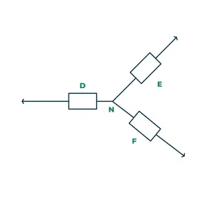
Three Phase Balanced Load
120 Degree Conduction Mode
In this conduction mode , each electronic device operates for 120 degrees , making it suitable for a delta connected load . This mode generates a six step waveform across one of its phases , where only specific devices conduct at any given instant , precisely at 120 degree intervals. In the load connection , the ‘D’ terminal connects to the positive end of the source , while the ‘E’ terminal links to the source negative terminal . The ‘F’ terminal remains in a floating state , meaning it is not connected to either the positive or negative side of the source .The phase voltages across the load correspond to the voltages , providing a controlled and balanced output across the phases.

Switching Pattern for 120 Degree Conduction Mode
phase voltages are equal to line voltages.
VDE = V
VEF = -V/2
VFD = – V

120 Degree Conduction Waveform
From the above waveform :
- From 0-60 : s1 and s6 are in conduction while remaining switches are opened.
- From 60 – 120 : s1 and s2 are in conduction while remaining switches are opened.
- From 120 – 180 : s3 and s2 are in conduction while remaining switches are opened .
- From 180 – 240 : s3 and s4 are in conduction while remaining switches are opened.
- From 240 – 300 : s5 and s4 are in conduction while remaining switches are opened.
- From 300 – 360 : s5 and s6 are in conduction while remaining switches are opened.
Advantages of 3-Phase Inverter
- A three phase inverter transmits more power over long distances compared to single phase power.
- Three phase inverter has high efficiency due to the balanced load distribution across all the three phases . So, that it leads to reduced energy loss and power operating costs.
- Three phase inverters provide more stable and balanced output voltage and current which leads to better power quality.
- Three phase inverters can help in minimizing harmonic distortion in electrical systems which reduces power quality.
- Three phase inverters are less affected by overvoltage events .
- Three phase inverters are more compatible with electrical grid.
- Three phase inverters can be smaller and lighter than the single phase inverters.
Disadvantages of 3-Phase Inverter
- These are more expensive due to complex design , additional complexity and higher power capacity .
- These are more complex to install due to and require careful attention to phase balancing and load distribution which requires experienced users .
- These are larger and heavier that make installation and maintenance more difficult .
- These inverters can sometimes produces electromagnetic interference which may effects electronic devices and systems .
- These are used in high power applications and may not be efficient when operating low power levels which leads lo energy wastage in smaller installations.
Applications of 3-Phase Inverter
- Three phase inverters are used in variable frequency drive applications .
- These are used in high power applications like HVDC power transmission.
- These are used in agriculture for irrigation pumps and other farming practices.
- These are used to power heavy machinery such as crushers , conveyors etc.
- These are used in electric vehicles i.e. for converting DC power from vehicle’s battery into three phase AC power to drive the electric motor .
- These are used to control and power electric motors and are found in pumps , fans , conveyors , manufacturing equipment etc.
Solved Example of 3-Phase Inverter
1. A single phase half bridge inverter has a resistance of 5 ohms and input DC voltage as 100V . Calculate
- the rms voltage occurring at the fundamental frequency
- output power
- peak current
- average current
- Harmonic rms voltage
- total harmonic distortion
Solution : Given R = 5 ohms , E = 100V
- The rms voltage occurring at the fundamental frequency E1RMS = 0.9 * 100 = 90v
- RMS output voltage = E0RMS = E = 100v
- output power = E^2 /R = (100)^2 / 5 = 2000W
- Peak current Ip = E0/R = 100/5 = 20A
- Average current = Ip/2 = 20/2 = 10A
- Harmonic RMS voltage En = { (E0RMS)^2 – (E1RMS)^2 }^0.5 = [(100)^2 – (90)^2]^0.5 = 43.588v
- Total harmonic distortion = En/E1RMS = 43.588/90 = 0.4843 * 100% = 48.43%
Conclusion
Thus this is an overview of three phase inverter- types , working , advantages , limitations , applications. Three-phase inverters find extensive use in variable-frequency drives (VFDs) , which are essential for controlling the speed and torque of electric motors in industrial and commercial settings . Additionally , these inverters are prominently featured in high-power applications such as high voltage direct current (HVDC) power transmission , where they play a crucial role in converting DC power from source like power plants or renewable energy systems into AC power suitable for long-distance transmission . The three-phase inverter is a versatile and indispensable component in the realm of power electronics . It facilitates the conversion of DC voltage into 3-pase AC power , with applications spanning variable-frequency drives and high-power scenarios , notably in HVDC power transmission , contributing significantly to the efficiency and control of various electrical systems.
FAQs on 3-Phase Inverter
Are three-phase inverters more complex to install than single phase inverters ?
Three-phase inverters may require additional wiring and configuration compared to single phase inverters due to the three- phase power distribution.
Can three-phase inverters be used in off-grid configuration ?
Yes , three-phase inverters can be used in off-grid applications , but they are often used in grid-tied systems . Specialized off-grid inverters are also available .
Do three-phase inverters produce harmonics in the output waveform ?
While , three-phase inverters can produce cleaner output waveforms , they may still introduce some harmonics . To minimize harmonics , appropriate filtering or PWM control technique can be employed .
Share your thoughts in the comments
Please Login to comment...