Parametric Modeling in Computer Graphics
Last Updated :
21 Nov, 2023
In this article, we will cover all the necessary detail that is acquired to know about Parametric Modeling. Let’s start with the simple definition, just go through all the points and headings. It will give you a brief intro about what is parametric modeling and why we use it.
Parametric Modeling
It is a term used to demonstrate the ability which change the model geometry’s shape while the dimension value is changed. Various component of a model is described by the feature-based.
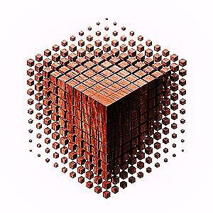
Parametric shape
For Instance: An object can be included with various types of features like grooves, chamfers, holes, and fillets. The parametric solid model consists of a basic unit called ‘Feature’.
Main Purpose of Parametric Modeling
Objects and systems are designed by the computer using parametric modeling with component properties that stimulate real-world behavior. To manipulate the system attributes, parametric modeling uses feature-based, surface, and solid modeling design tools. There is one of the most essential features of parametric modeling is the automatic change in the features that are interlinked, or we can say that it allows the designer to demonstrate all classes of shapes except by giving instances of them. It was difficult for designers to change the form before the invention of parametrics.
For Instance: the designer had to alter the length, breadth, and height of a 3D solid. However, using parametric modelling, the designer only needs to change one parameter since the other two are automatically updated. Therefore, parametric models emphasise and parameterize the phases involved in shaping an object. Product design engineering service companies gain a lot from this.
Process of Parametric Modelling
A series of mathematical equations serve as the foundation for parametric models. Parametric models must be based on accurate project data in order to be taken seriously. The effectiveness of a modeling solution is determined by the level of expertise of the information analysis approaches and the depth of the hidden undertaking information.
Types of Parametric Models
There are two types of Parametric Models. These are discussed below:
- Constructive Solid Geometry (CSG)
- Boundary Representation (BR)
Constructive Solid Geometry (CSG)
CSG (Constructive Solid Geometry) defines a model by Combining fundamental (primitive) and created (using extrusion and sweeping operations) solid shapes. It builds a model using Boolean operations. CSG is made up of a collection of 3D solid primitives, such as a cone, cylinder, prism, rectangle, or sphere, which are then worked with using basic Boolean operations.
Boundary Representation (BR)
In BR (Boundary Representation), a solid model is created by specifying the surfaces (points, edges, etc.) that define its spatial limits. Then, by connecting these spatial points, the thing is created. This technique is widely used in Finite Element Method (FEM) programmes because it makes it easier to manage the interior meshing of the volume.
Advantages of Parametric Modeling
The advantages of 3D parametric modeling over conventional 2D drawings are as follows:
- It is able to create flexible designs
- Enhanced product visualisation because you can start with basic objects and little detail
- Enhanced downstream application integration and shortened engineering cycle time
- New designs can be made using already created design data.
- Rapid design turnaround, efficiency improvement
Terminologies Related to Parametric Modeling
- Parametric Model: Its like a 3D (3-dimenstional) model which has parameters that can be customize according to our requirement. We can easily change the values in the parameter to create change in shape, dimensions and other properties of our model.
- NURBS Model: It is a mathematical approach which is used in CAD and also in computer graphics. We can control its curve or we can say the surface through the use of control points.
- Polygonal Model: Polygonal Model is also known as Mesh Model. It is type of model that is used to create 3D objects by using tiny components. These components or polygons are consist of edges, vertices and faces. Also keep in mind that a single polygon is usually said to be a Face. Though a Polygon Mesh consist of many connected faces (polygon). We can use it to build a 3D polygon model.
- Visual Programming: It allows us to create parametric 2D or 3D models by inserting nodes, setting, changing parameters and connected inputs. It is best for the people who usually don’t have coding skills because it make the user to utilize the power of algorithms with actions and visual objects rather than a script of code.
- Nodes: We can also say it as components. They process and contain a sequence of data about parameters of a model.
- List: It can be defined as a collection of items that can be utilize as a input or output source, managed in a structured way by using indexes which starts from 0.
- Data Types: Each and every item has its own data type. Some items consist of curves, points , some consist of solids and other contains only numbers , it can be vary according to the parametric modeling software.
Parametric Modelling Tools
Today’s market offers a wide variety of software options for parametric modelling. This programme can be broadly categorised as:
- Small Scale Use
- Large Scale Use
- Industry Specefic Modeling
The third category, Industry-Specific Parametric Software, has seen the most growth. Some of the top business software includes:
- SolidWorks: SolidWorks, which was first released in 1995 as a low-cost alternative to the other parametric modelling software solutions, was acquired by Dassault Systemes in 1997. It has a large following in the plastics industry and is mainly employed in mechanical design applications.
- CATIA: CATIA was developed by Dassault Systemes in France in the late 1970s. These complex industries—aeronautics, automobiles, and shipbuilding—all make extensive use of this software.
- PTC: The industry standard for 3D CAD software is Creo Parametric. To speed up the design of components and assemblies, it offers the widest variety of potent yet adaptable 3D CAD capabilities.
FAQs on Parametric Modeling
1. What is Difference between Parametric and Direct Modeling?
|
Parametric modelling is a 3D CAD technique that enables users to automate recurring modifications, with the use of features and restrictions, such as those present in families of product parts.
|
You can specify and capture geometry more quickly using direct modelling since you don’t have to worry about features, limitations, or the original design intent. It’s frequently contrasted with working with modelling clay. To achieve the desired shape, simply push and drag the geometry.
|
2. What are the free software for Parametric modeling?
FreeCAD,Onshape,Creo Parametric are some of the quite famous software used in Parametric Modeling.
3. What is the parametric modeling cost?
To determine the anticipated amount of resources—such as money, time, or even human resources—necessary to execute your project, parametric estimating, a quantitative technique, uses statistics.
4. What is the difference between parametric and nonparametric Modelling?
The assumption of a parametric model is that a probability distribution with a defined set of parameters can accurately represent the population. A non-parametric model makes no assumptions on any probability distribution during modelling the data.
Share your thoughts in the comments
Please Login to comment...