Non-binary Counter in Digital Logic
Last Updated :
26 Oct, 2022
A counter is a circuit that counts the number of occurrences of an input. The circuit consists of flip-flops which along with combinational elements are used for generation of control signals.
If M = Total number of states, and
   n = Total number of flip-flop
Then,      M <= 2n
If         M = 2n    ; Binary counter
and        M < 2n    ; Non-binary counter
Block Diagram of Non-Binary Counter: Here is the block diagram of a mod-10 counter. Here, the total number of flip-flops required is 4 thus the number of used state is 10 and number of unused state is 6. 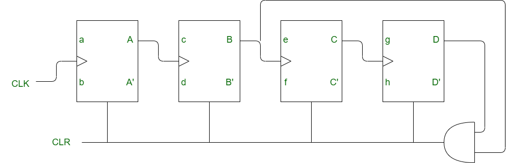 In order to design a non binary counter a logic gate is required which detects M stage. In mod-10 counter 10 stages are detected from 0000 to 10001 and as soon as 1010 appears it clears all the flip-flops. Making of Non-binary counter: For making non-binary counter,
- If CLR is present and CLK is connected with output Q, then we use AND gate.
- If CLR is present and CLK is connected with output Q’, then we use NOR gate.
- If complement of CLR is present and CLK is connected with output Q, then we use NAND gate.
- If complement of CLR is present and CLK is connected with output Q’, then we use OR gate.
Truth Table: 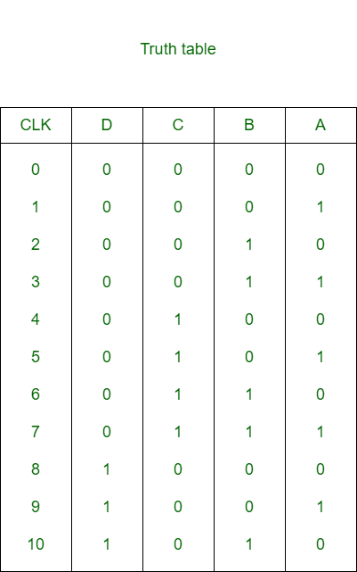 It is clear from truth table that as soon as 1010 appears, inputs to the AND gate becomes 11 which resets the flip-flop with CLR =1. Output Frequency: The output frequency of mod-M counter,
= f / M
If there is no feedback present at last output (i.e D) then the output frequency,
= f / (2n)
Share your thoughts in the comments
Please Login to comment...