Implementing 32:1 Multiplexer using 8:1 Multiplexers
Last Updated :
15 Jun, 2022
A multiplexer is a digital combinational circuit that selects one out of several input lines and directs it to a single output line, hence often alternatively called a data selector. The selection of a particular input line out of several choices takes place on the basis of the selector lines. A multiplexer, in general, has n input lines, log2n selector lines, 1 enable line, and 1 output line and is commonly called an n:1 Multiplexer.
An interesting problem in digital electronics is to make a p:1 multiplexer using only a q:1 multiplexer. The general methodology to tackle such problems is to divide n by m until we get 1 and find the number of stages and the number of multiplexers required.
p/q = k1            Stage 1
k1/q = k2           Stage 2
k2/q = k3           Stage 3
   :                   :
kn-1/q = kn = 1      Stage n
We have n stages, and the ith stage has ki = p/qi number of multiplexers.
This works only when p is the n-th power of q. That is p = qn. So, log2p = nlog2q.
Hence the number of selector lines in the p:1 multiplexer must be an integral multiple of the number of selector lines in the q:1 multiplexer. The integer n is basically the number of stages.
Total number of multiplexers = k1+k2+…+kn-1+1 = p/q + p/q2+…+p/qn-1+p/qn
We immediately see it’s a geometric series. Hence.
Total number of multiplexers = (p-1)/(q-1) = (qn -1)/(q-1) .
Here’s an example of implementing 8:1 Multiplexer using 2:1 Multiplexers.
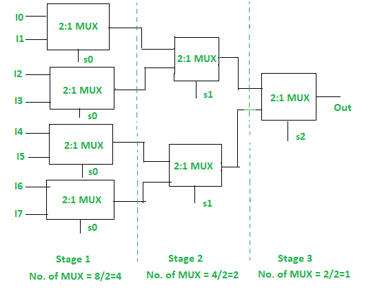
8:1 MUX using 2:1 MUX
However, if p is not an n-th power of q, then we cannot follow this simple implementation procedure. In such cases, we have to use the enable input. In general, we will have log2q selector lines and the rest r selector lines will be provided through the enabling, where r=log2p – log2q.
A 32:1 Multiplexer has 32 input lines and log2 32 = 5 selector lines.
A 8:1 Multiplexer has 8 input lines and log2 8 = 3 selector lines.
32/8 = 4, so four 8:1 Multiplexers are needed, but they have insufficient selector lines. So, we need to put 2 extra selector lines. In order to accommodate the 2 other selector lines, we need to use the enable (E) input of the multiplexers.
Truth Table of 32:1 Multiplexer:
| S4 |
S3 |
S2 S1 S0 |
Output |
| 0 |
0 |
0 0 0
: : :
1 1 1
|
I0
:
I7
|
| 0 |
1 |
0 0 0
: : :
1 1 1
|
I8
:
I15
|
| 1 |
0 |
0 0 0
: : :
1 1 1
|
I16
:
I23
|
| 1 |
1 |
0 0 0
: : :
1 1 1
|
I24
:
I31
|
I signify the input line.
Truth Table of 8:1 Multiplexer:
| S2 |
S1 |
S0 |
Output |
| 0 |
0 |
0 |
I0 |
| 0 |
0 |
1 |
I1 |
| 0 |
1 |
0 |
I2 |
| 0 |
1 |
1 |
I3 |
| 1 |
0 |
0 |
I4 |
| 1 |
0 |
1 |
I5 |
| 1 |
1 |
0 |
I6 |
| 1 |
1 |
1 |
I7 |
I signify input line.
Implementation:
From the truth table, we can see that the truth table of the 32:1 Multiplexer is similar to the 8:1 Multiplexer for each combination of S4 and S3. So, if we enable only one out of the four 8:1 Multiplexers at a time using the enable E, then the 32:1 Multiplexer can be realized easily.
SOP expression of the 32:1 Multiplexer is:
O = S4’S3’D0 + S4’S3D1 + S4S3’D2 + S4S3D3
Where each D is the output for each 8:1 multiplexer.
D0 = S2'S1'S0'I0 + S2'S1'S0I1 + S2'S1S0'I2 + S2'S1S0I3 + S2S1'S0'I4 + S2S1'S0I5 + S2S1S0'I6 + S2S1S0I7
D1 = S2'S1'S0'I8 + S2'S1'S0I9 + S2'S1S0'I10 + S2'S1S0I11 + S2S1'S0'I12 + S2S1'S0I13 + S2S1S0'I14 + S2S1S0I15
D2 = S2'S1'S0'I16 + S2'S1'S0I17 + S2'S1S0'I18 + S2'S1S0I19 + S2S1'S0'I20 + S2S1'S0I21 + S2S1S0'I22 + S2S1S0I23
D3 = S2'S1'S0'I24 + S2'S1'S0I25 + S2'S1S0'I26 + S2'S1S0I27 + S2S1'S0'I28 + S2S1'S0I29 + S2S1S0'I30 + S2S1S0I31
The implementation is shown below.
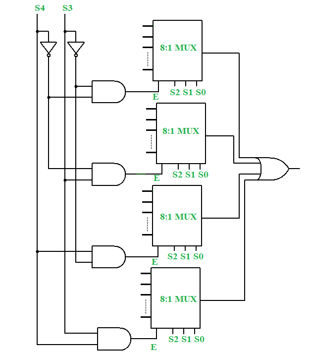
32:1 Multiplexer using 8:1 Multiplexer
Share your thoughts in the comments
Please Login to comment...