Blink LED in Arm Cortex Microcontroller using Keil software
Last Updated :
27 Feb, 2024
The ARM Cortex-M4 is a 32-bit processor core that is widely used in microcontrollers for embedded systems. It is designed to be highly efficient, and low-cost. The Cortex-M4 architecture is based on the ARMv7 instruction set architecture and It’s capable of handling up to 4GB of memory address space.
In this tutorial, we will demonstrate how to blink the inbuilt LED of an ARM Cortex M4 microcontroller using the Keil software and the C programming language.
Required Software and Hardware
- Keil (MDK-ARM) – This is the software used for programming in ARM-based Microcontrollers. Make sure to install the STMicrocontroller library inside it.
- ARM Cortex M4 microcontroller (STM32F407xx) – This is the hardware that we will be programming.
About Keil Software
Keil uVision is a software development environment that comes with project management, and a powerful, contemporary editor. It contains various tools required to create embedded applications.
µVision offers the following features, which facilitate the development of embedded applications more quickly:
- A feature-rich editor for source code.
- Device Databases for setting up the tool for development.
- A project manager to help you start and finish your work.
- Integrated capabilities for linking, assembling, and compiling your embedded applications with the Make Utility.
- Dialogs for every setting in the development environment.
- A real combined source-level and assembler-level debugger, along with a fast peripheral simulator and CPU.
- Advanced GDI interface for connecting to a Keil ULINK Debug Adapter and software debugging on target hardware.
- A tool for flash programming that allows you to download applications into Flash ROM.
- Connections to user manuals, device datasheets, online assistance, and manuals.
Programmers may quickly and successfully design embedded applications with the help of the many features offered by the µVision IDE and Debugger, which is the core of the Keil development toolchain. You may accomplish your design objectives quickly and easily with the aid of the user-friendly Keil tools.
µVision has a Debug Mode for debugging applications and a Build Mode for generating new ones. Software can be debugged directly on hardware using tools like ULINK Debug , Trace Adapters, or integrated with the µVision Simulator. Other adapters and external third-party tools are available for developers to employ in order to assess programs.
STM32F407xx MicroController
STMicroElectronics’ STM32F407xx family is based on the high-performance 32-bit RISC engine ARM® CortexTM-M4, operating at frequencies up to 168 MHz. The single-precision floating point unit (FPU) in the Cortex-M4 core supports all ARM single-precision data processing instructions and data inputs. It also uses the Memory Protection Unit (MPU) and all DSP commands to secure the application.
The STM32F407xx series includes two APB buses, three AHB buses and a 32-bit multi-AHB bus matrix, as well as a variety of I/O upgrades and peripherals. It also includes high-speed onboard storage (up to 1 MB flash memory, up to 192 KB SRAM), up to 4 KB spare SRAM, and more. The entire hardware includes three 12-bit ADCs, two DACs, one low-power RTC, 12 target 16-bit timers (including two PWM timers for motor control), two target 32-bit timers and a true random number generator (RNG). ). They also have sophisticated and complex communication skills.
Based on the ARMv7 instruction set, this microcontroller is popular in embedded systems due to its cost effectiveness, performance and 32-bit processing capability. The special model STM32F407xx has features suitable for many applications.
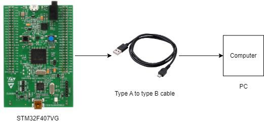
Circuit Diagram
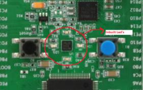
Inbuilt Led location for reference:
The Above circuits Diagrams
- At the core of the circuit lies the ARM Cortex-M4 Microcontroller (STM32F407xx). It follows specified orders to run the LED.
- A Type A to Type B Cable is used here. It links the microcontroller to the PC- acting as a bridge for programming and identifying errors. This cable facilitates both data movement and power supply to the microcontroller. One end of the cable plugs into the PC and the other into the microcontroller.
- The built-in LED of the microcontroller is the end product for this project. This LED illuminates when the corresponding GPIO pin is activated to high.
Connection Steps
- Connect PC to the microcontroller using a Type A to Type B USB cable. This connection enables the Keil software to communicate with the microcontroller for various functionality.
- See the inbuilt LED on STM Microcontroller which will glow/blink with the delay according to the program written by the user.
- Program and configure the STM32F407xx microcontroller with the help of Keil Software.
- Flash the code to the microcontroller after compiling the code successfully and doing necessary configuration settings.
- The inbuilt LED on the microcontroller should start blinking according to the program flashed into it. This shows that the setup is good and working correctly.
Steps for Interfacing
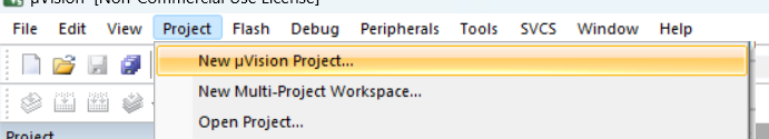
1.Open Keil software ->project->New uVisionProject.
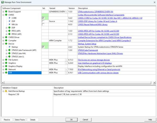
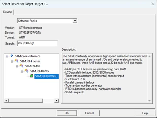
2.Check the following options as shown and click on OK.
3.Type stm32f407vgtx in search bar click on OK
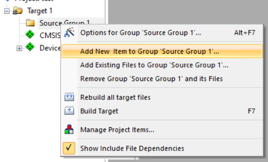
4. On the left panel right click on source group and click on add new item as shown.
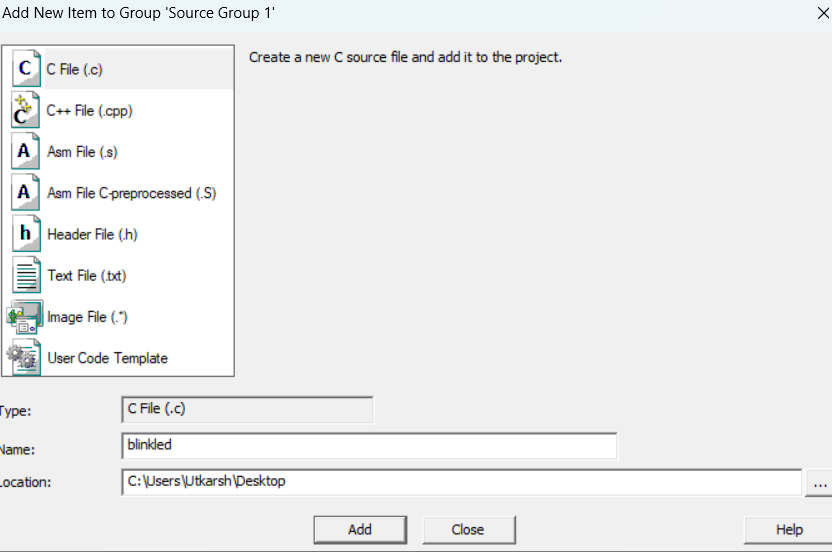
5. Click on C file and give a name and click on OK.
6.Write the following code in the writing are and save it and also connect the Microcontroller to the pc.
C
#include "stm32f4xx.h"
void delay (int n);
int main(void) {
RCC->AHB1ENR |=8;
GPIOD->MODER |=0X55000000;
while(1) {
GPIOD->ODR ^=0X0000F000;
delay(300);
}
}
void delay(int n){
int i,j;
for(j=0;j<n;j++)
for(i=0;i<3195;i++);
}
|
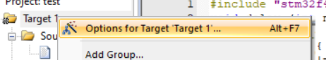
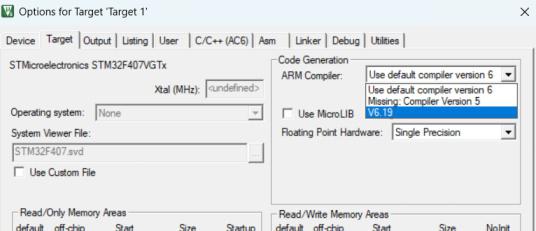
7. Now again in left panel right click on Target and select options for Target.
8. Go to Target tab and choose V6.19 in ARM compiler.
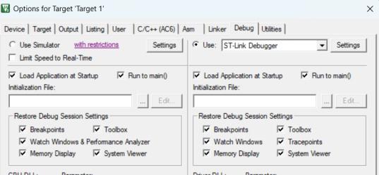
9.Now to to Debug tab Use-> ST-Link Debugger. And click on settings.
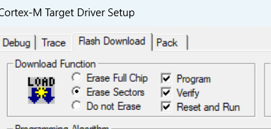
10.Go to Flash Download -> Check Reset and run. Click on OK in all.
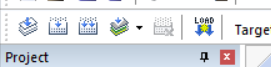
11. Press ctrl + s to save. Build the project and verify. i.e click on first three options one by one after each gets completed without any error. And click on load.
You can see the internal LED Blinking on the microcontroller.
Conclusion
In this tutorial, we have successfully demonstrated how to blink the inbuilt LED of an Arm Cortex M4 microcontroller using the Keil software and the C programming language. By following the step-by-step instructions outlined above, you should now have a working understanding of creating a new project, configuring the target settings, writing and saving C code, and using the ST-Link Debugger for flashing the microcontroller. This project serves as a foundational exercise for those venturing into embedded systems and microcontroller programming.
FAQs on Blink LED in Arm Cortex Microcontroller using Keil software
What is a microcontroller?
It is basically a small computer that consists of integrated circuit contains processor, memory and input/output peripherals. It is widely used in embedded systems for various applications.
What is purpose of blinking LED in the tutorial?
It helps in understating the fundamental concepts of the embedded programming. It shows how to manipulate the GPIO pins according to the user requirements, with the help of C programming.
How to expand the project?
You can try implementing various other sensors/actuators (like temp , humidity sensors) along with various LED blinking patterns and program it accordingly to see the desired output.
Share your thoughts in the comments
Please Login to comment...