Implementation of Full Adder using NOR Gates
Last Updated :
25 Apr, 2024
In Digital Logic Circuit, Full Adder is a Digital Logic Circuit that can add three inputs and give two outputs. The three inputs A, B, and input carry as Cin. Cout is represented as output carry and Sum is represented as output. We can say Cout is called the majority 1’s detector, when more than one input is high (logic 1) then its output will be high.
In Digital Logic Circuits, Full Adders are implemented using digital logic gates such as OR gate, AND gate, NOT gate, NAND gates, NOR gates, etc. In this article, we will explore Full Adders, and NOR Gates and execute the Implementation of Full Adders using NOR Gates.
What is a Full Adder?
Full Adder is a Digital Logic circuit that can add three inputs and give two outputs i.e. three inputs such as A, B, and input carry as Cin, and gives a sum output and carry output i.e. two outputs. A Full Adder Circuit performs as the brain of most Digital Logic Circuits that execute addition or subtraction. Full adders are used in multiplexers and Demultiplexers to choose and course information.
A Full Adder requires the use of nine NOR gates. The Arithmetic Logic Unit, ALU uses Full Adders. In a computer, Full Adders are utilized by the ALU to produce memory addresses and relocate the Program Counter to the next instruction.
Now, Here we will understand Full Adder by Block Diagram of Full Adder where we will discuss and explain it by using :
- Truth Table of Full Adder
- Logical Expression for Full Adder
Block Diagram of Full Adder
The Block Diagram and Truth Table of Full Adder is shown below :
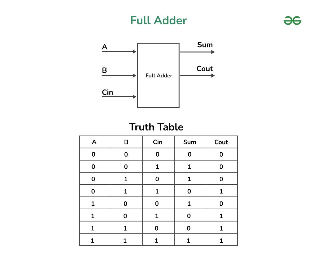
Full Adder
Logical Expression for Full Adder
Given below is the Expression for Full Adder which includes Sum and Carry :
Sum=A ⊕ B ⊕ Cin
Cout= AB + ACin + BCin
Where, A, B, Cin are the Inputs of the Full Adder
Applications of Full Adder
- Arithmetic Circuits: Full adders are used in arithmetic circuits to add two double fold numbers. We can say when different Full Adders are connected in a series, they can evaluate numerous-bit paired numbers.
- Data Handling: Full adders are used in information handling applications such as advanced signal manipulation, encoding of information, and mistake correction.
- Counters: Full adders are used in counters to perform addition or decrement the count by one.
- Multiplexers and Demultiplexers: Full adders are used in multiplexers and Demultiplexers to choose and course information.
- Addressing Memory: In Memory Addressing circuits, Full adders are operated to induce the site of a memory area.
- ALUs: Full adders are used as a basic part of Number juggling Rationale Units (ALUs) used in chip and computerized signal processors.
What is a NOR Gate?
In Digital Electronics, Logic gates are one of the most important component. It basically works on the theory of boolean function. In Digital Electronics, There are various NOR Gates, which is also comes under Universal Gate because it can be utilized to execute other basic logic gates like AND, OR and NOT gate by connecting NOR gates with each other in particular configurations.
NOR gate is a digital logic gate that executes NOR operation between two or more binary inputs and output binary signal. NOR Gate is a combination of OR gate and NOT gate.
It has multiple inputs that are executed to give the output complemented to OR Gate So, It has a Universal gate property. So that it is operated as the complement of OR gate that can be used in memory circuits.
When both the Inputs are connected to the gate are Low (logic 0) then it results as High (logic 1)
And, if one or both inputs is High (logic1) then it results as Low (logic 0)

NOR Gate
Logical expression of a NOR Gate
Boolean expression of a NOR Gate is mentioned below
In the expression, Two inputs are represented as A and B and the Output is O, then the expression is –
O = (A+B)’
Applications of NOR Gate
- Inverter Function: In Inverter function, A NOR gate with single-input can operate as an inverter or NOT gate. When an input signal is associated with one input and ground (0V) is associated to other input , then the output will be the inverse of the input.
- Memory Components: NOR gates are significant in making basic memory elements like SR and D latches, giving as basic building blocks for complicated digital circuits and memory units.
- Boolean Logic: NOR gates compete an essential role in executing many Boolean logic functions. They can be merged in many ways to construct AND, OR, and NOT gates, building the foundation for all logic operations.
- Decoders: NOR gates are important elements in decoder circuits, which transforms binary information into an expanded form, simplifying work like memory addressing and output selection.
- Arithmetic Circuits: NOR gates are important resources in the configuration of an arithmetic circuits such as adders and subtractors, executing logical operations on binary numbers.
- Programmable Logic Devices (PLDs): NOR gates are oftenly highlight in PLDs to recognize custom logic functions, building them flexible components in digital circuit design.
- Clock Circuits: NOR gates put up to clock generation and distribution circuits in digital systems, certifying synchronization and exact timing control.
- Error Detection: In particular error-detection codes like Reed-Solomon codes, NOR gates are associated for computing the checking of parity bits and error correction in data transmission.
Implementation of Full Adder using NOR Gates
Implementation of Full Adder using NOR Gates is realization of Full Adder by using minimum nine NOR Gates during which we will have 2 outputs at the end namely Cout and Sum.
Given Below is the Circuit For Implementation of Full Adder using NOR Gates
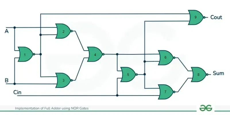
Implementation of Full Adder using NOR Gates
Logical Expression for Full Adder using NOR Gate
Now, we are going to find the Logical expression of Full Adder using NOR Gate.
We know that,
Logical expression of XNOR gate is
Y=A⊙B=[Tex]AB+\overline{A}.\overline{B}[/Tex]
where, A and B are inputs and Y is the output
Steps for Implementation of Full Adder using NOR Gates
Now, We are implementing Full Adder using NOR Gates,
- First input of Gate 1 is A and second input of Gate 1 is B so the Output of Gate 1 =[Tex]\overline{A+B}[/Tex]
- First input of Gate 2 is A and second input of Gate 2 is [Tex]\overline{A+B}[/Tex] so the Output of Gate 2 =[Tex]\overline{A+(\overline{A+B})}[/Tex]=[Tex]\overline{A+(\overline{A}.\overline{B})}[/Tex]=[Tex]\overline{A}.\overline{(\overline{A}.\overline{B})}[/Tex]=[Tex]\overline{A}.(A+B)[/Tex]=[Tex]\overline{A}B[/Tex]
- First input of Gate 3 is B and second input of Gate 3 is [Tex]\overline{A+B}[/Tex] so the Output of Gate 3 =[Tex]\overline{B+(\overline{A+B})}[/Tex]=[Tex]\overline{B+(\overline{A}.\overline{B})}[/Tex]=[Tex]\overline{B}.\overline{(\overline{A}.\overline{B})}[/Tex]=[Tex]\overline{B}.(A+B)[/Tex]=[Tex]A\overline{B}[/Tex]
- First input of Gate 4 is [Tex]\overline{A}B[/Tex] and second input of Gate 4 is [Tex]A\overline{B}[/Tex] so the Output of Gate 4 =[Tex]\overline{\overline{A}B+A\overline{B}}[/Tex]=[Tex](\overline{\overline{A}B}).(\overline{A\overline{B}})[/Tex]=[Tex](A+\overline{B}).(\overline{A}+B)[/Tex]=[Tex]AB+\overline{A}.\overline{B}[/Tex]=A⊙B
- First input of Gate 5 is [Tex]AB+\overline{A}.\overline{B}[/Tex] and second input of Gate 5 is [Tex]Cin[/Tex] so the Output of Gate 5 =[Tex](\overline{AB+\overline{A}.\overline{B})+Cin}[/Tex]=[Tex](\overline{AB+\overline{A}.\overline{B})}.\overline{Cin}[/Tex]=[Tex](\overline{AB+(\overline{A+B})}).\overline{Cin}[/Tex]=[Tex]\overline{AB}.(\overline{\overline{A+B}}).\overline{Cin}[/Tex]=[Tex](\overline{A}+\overline{B}).(A+B).\overline{Cin}[/Tex]=[Tex](\overline{A}B+A\overline{B}).\overline{Cin}[/Tex]
- First input of Gate 6 is [Tex]AB+\overline{A}.\overline{B}[/Tex] and second input of Gate 6 is [Tex](\overline{A}B+A\overline{B}).\overline{Cin}[/Tex] so the Output of Gate 6 =[Tex]\overline{(AB+\overline{A}.\overline{B})+(\overline{A}B+A\overline{B}).\overline{Cin}}[/Tex]=[Tex](\overline{AB+\overline{AB})}.(\overline{\overline{A}B+A\overline{B}).\overline{Cin}}[/Tex]=[Tex](\overline{A}B+A\overline{B}).(AB+\overline{A}.\overline{B}+Cin)[/Tex]=[Tex]\overline{A}BCin+A\overline{B}Cin=(\overline{A}B+A\overline{B}).Cin[/Tex]
- First input of Gate 7 is [Tex](\overline{A}B+A\overline{B}).\overline{Cin}[/Tex] and second input of Gate 7 is [Tex]Cin[/Tex] so the Output of Gate 7 =[Tex](\overline{(\overline{A}B+A\overline{B}).\overline{Cin}}).\overline{Cin}[/Tex]=[Tex](\overline{A}.\overline{B}+AB+Cin).\overline{Cin}[/Tex]=[Tex](\overline{A}.\overline{B}+AB).\overline{Cin}[/Tex]
- First input of Gate 8 is [Tex](\overline{A}B+A\overline{B}).Cin[/Tex] and second input of Gate 8 is [Tex](\overline{A}.\overline{B}+AB).\overline{Cin}[/Tex] so the Output of Gate 8 =[Tex]\overline{(\overline{A}B+A\overline{B}).Cin+(\overline{A}.\overline{B}+AB).\overline{Cin}}[/Tex]=[Tex](\overline{(\overline{A}B+A\overline{B})Cin}).(\overline{(\overline{A}.\overline{B}+AB).\overline{Cin}})[/Tex]=[Tex](\overline{(\overline{A}B+A\overline{B})}+\overline{Cin}).((\overline{\overline{A}.\overline{B}+AB)}+\overline{\overline{Cin}})[/Tex]=[Tex](AB+\overline{A}.\overline{B}+\overline{Cin}).(\overline{A}B+A\overline{B}+Cin)[/Tex]=[Tex]ABCin+\overline{A}.\overline{B}Cin+\overline{A}B\overline{Cin}+A\overline{B}.\overline{Cin}[/Tex]=[Tex](AB+\overline{A}.\overline{B})Cin+(\overline{A}B+A\overline{B}).\overline{Cin}[/Tex]=[Tex]\overline{(\overline{A}B+A\overline{B})}.Cin+(\overline{A}B+A\overline{B}).\overline{Cin}[/Tex]=A⊕B⊕Cin
- First input of Gate 9 is [Tex](\overline{A}B+A\overline{B}).\overline{Cin}[/Tex] and second input of Gate 9 is [Tex]\overline{A+B}[/Tex] so the Output of Gate 9 =[Tex]\overline{(\overline{A}B+A\overline{B}).\overline{Cin}+(\overline{A+B})}[/Tex]=[Tex](\overline{(\overline{A}B+A\overline{B})\overline{Cin}}).\overline{(\overline{A+B})}[/Tex]=[Tex](\overline{(\overline{A}B+A\overline{B})}+\overline{\overline{Cin}}).(A+B)[/Tex]=[Tex](AB+\overline{A}.\overline{B}+Cin)(A+B)[/Tex]=AB+ AB+ ACin + BCin = AB + ACin + BCin
- So, the Expression for Sum=A⊕B⊕Cin i.e. The Expression for Output Gate 8
- So, the Expression for Cout=AB+ACin+BCin i.e. The Expression for Output Gate 9
Conclusion
Here, we saw how we can use a universal gate called the ‘NOR’ gate to implement the Full Adder. This is important as it helps us analyze the working behind universal gates and we can understand how we can implement Full Adder using universal gates. The implementation of a full adder using NOR gates can be achieved by combining multiple NOR gates based on the logical expressions for the Sum and Cout outputs.
NOR gates are sometimes considered more intuitive and easier to use in certain logic functions. For example, NOR gates are directly associated with the OR function, and their use can simplify the design of circuits where OR logic is predominant. NOR gates might have a shorter propagation delay NOR gates may offer better timing characteristics.
Depending on the design requirements and specific configurations, NOR gates may lead to circuits with a lower transistor count. This reduction in transistor count can have advantages in terms of power consumption and area efficiency. It is instructed that readers go through all other realizations to understand the basic functioning behind other important gates. FAQ’s have been responded that enfold some fundamental opinions. Readers can also refer to these questions as well.
Implementation of Full Adder using NOR Gates – FAQs
Why is NOR Gate known as Universal Gate?
NOR Gate is known as Universal Gate because it produces basic logic gates like AND gate, OR gate, and NOT gate in the absence of any other gates.
What is the Expression for Sum in Full Adder?
The expression for Sum in Full Adder is:
S = A ⊕ B ⊕ Cin
What is the Expression for Cout in Full Adder?
The expression for Carry, Cout in Full Adder is:
Cout = AB + ACin + BCin
How many minimum NOR gates are required to achieve Full Adder?
To implement Full Adder using NOR gates we require nine NOR gates.
Can a NOR Gate be used as an inverter?
An Inverter or logic NOT gate can also be made using standard NOR gate by connecting together all their inputs to a common input signal.
Share your thoughts in the comments
Please Login to comment...