Voltage Multipliers
Last Updated :
27 Feb, 2024
Voltage Multiplier Circuits are very essential components in electrical engineering which provides a means to boost the voltage levels of various applications. These circuits are very useful in various fields ranging from power supplies to various electronic devices. Understanding their types of working principles and applications is important for engineers as it plays an important role in the electronics field.
In this article, we will be going through the Voltage Multiplier Circuit, First we will start with the Definition of the Voltage Multiplier, Then we will go through its Types Such as Half wave, Full Wave, Dc Voltage Tripler, Ac Voltage Tripler, At last we will Conclude our Article with its Advantages, Disadvantages, Application and FAQs.
What are Voltage Multiplier Circuits?
Voltage Multiplier Circuits are devices that are designed to generate an output voltage that is a multiple of the input voltage. They are often used to achieve higher voltage levels than older circuits that were developed in the past, especially in situations where efficiency and compact design are very critical. There are four types of voltage multiplier circuits named as Half Wave Voltage Double, Full Wave Voltage Doubler , Voltage Triple and Voltage Quadrupler.
Types of Voltage Multiplier Circuits
There are four types of voltage multiplier circuits named as :
- Half Wave Voltage Doubler
- Full Wave Voltage Doubler
- Voltage Tripler
- Voltage Quadrupler
Half Wave Voltage Doubler
A half-wave voltage doubler is a type of electronic circuit that is used to double the voltage of an alternating current or alternating signal. This half-wave voltage doubler consists of a diode and a capacitor. During the positive half cycle of the AC input, the diode allows current to charge the capacitor to a high voltage. During the negative half cycle, the diode does not allow the current while the capacitor discharges through a load doubling the voltage across the load. This circuit is simple but is not very efficient compared to other type of rectifiers.
Working of Half Wave Voltage Doubler
- During the positive half cycle the diode D1 gets forward baised and hence it conducts which charges C1 to its peak input voltage.
- During the negative half cycle the diode D1 gets reversed baised and it does not conduct and D2 gets forward baised and it conducts which transfers the charge from C1 to C2.
- The output voltage (Vout) across the C2 is approx twice of its peak input voltage.
Circuit Diagram of Half Wave Voltage Doubler

Half Wave Voltage Doubler
Full Wave Voltage Doubler
A full wave voltage doubler is a type of electronic circuit which is made to double the voltage of an alternating current or alternating signal. It is used as a bridge rectifier which consist of four diodes which are arranged in such a way that it rectifies both the positive and negative half cycles of the input signal. This charges the capacitor in both directions in both cycles doubling the voltage across the load. A full wave voltage doubler has high efficiency compared to half wave voltage doubler which provides a clean DC output which has less ripple factor.
Working of Full Wave Voltage Doubler
- During the positive half cycle diode D1 and D2 gets forward baised and hence they conduct which leads to charging of capacitor C1.
- During the negative half cycle diode D3 and D4 gets forward baised and hence they conduct which leads to doubling the voltage across the load (R).
- Output voltage (Vout) is approx twice the peak input voltage considering both the half cycles.
Circuit Diagram of Full Wave Voltage Doubler

Full Wave Voltage Doubler
Voltage Tripler
A voltage tripler is a type of electronic circuit which is made in such a way that it makes the voltage of an alternating current or alternating signal three times of input value. It uses a combination of diodes and capacitors to gain this type of voltage multiplication. This type of circuit also has a series of charging and discharging cycles through capacitors during different cycle of the AC signal. By making some proper connections of the components the voltage tripler produces an output voltage which is approx three times the value of the input AC voltage. This type of circuit is mainly used in high voltage applications because a high DC voltage is required.
Working of Voltage Tripler
- During the positive cycle diode D1 is forward biased and the diodes D2 and D3 are reverse biased due to which the capacitor C1 gets charged.
- During the negative cycle diode D2 is forward biased and other diodes are reversed baised due to this the Capacitor C2 gets charged. As the voltage across the capacitor C1 and the secondary transformer are additive in nature this makes the capacitor C2 also charge.
- During the another positive cycle capacitor C1 keeps its charge and hence the diode D1 does not conduct and capacitor C3 is not charged then due to this the conduction path for the positive cycle will be Capacitor C1, Capacitor C3, Diode D3 and Capacitor C2.
- Since D3 is forward biased capacitor C3 will charge 2 times which is the sum of secondary of transformer and voltage across the Capacitor C1. After taking the voltage across Capacitors C1 and C3 the voltage will be the sum of its individual capacitors. Therefore, the circuit functions as a voltage tripler..
Circuit Diagram of Voltage Tripler

Voltage Tripler
Voltage Quadrupler
A voltage quadrupler is an type of electronic circuit which is made in such a way that the voltage of an alternating current or alternating signal becomes four times of its input value. This circuit consists of a combination of diodes and capacitors to gain voltage multiplication. This process involves charging and discharging cycles in the capacitors during different cycles of the AC signal. After making proper connections of the components the quadrupler provides an output voltage that is approx four times the value of the input signal. This is type of circuit which is mainly used in applications where there is a need high DC voltage and also it provides a simple and also a very better way of achieving voltage multiplication.
Working of Voltage Quadrupler
- During the positive half cycle the diode D1 and D11 gets forward baised and hence they conduct which allows the capacitors C1 and C11 to charge from voltage of the input.
- During the negative half cycle the diode D2 and D22 gets forward baised and hence they conduct which allows the capacitors C2 and C22 to charge to the voltage of the input.
- Now during the next positive half cycle the input voltage becomes more positive due to which diode D1 and D11 become reverse biased and the voltage which is present across C1 and C11 gets doubled up which effectively doubles the voltage.
- Similarly during the next negative half cycle diode D2 and D22 become reverse biased and due to this the voltage across C2 and C22 gets doubled up which doubles the voltage.
- Hence there is a repetition of this process with positive and negative half cycle which leads to doubling the voltage across the capacitors.
- After finishing all the process the voltage across the load is four times of given input signal hence voltage gets quadrupled.
Circuit Diagram of Voltage Quadrupler
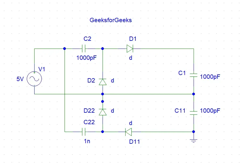
Voltage Quadrupler
Advantages and Disadvantages of Voltage Multiplier Circuit
Given Below Are Advantages and Disadvantages of Voltage Multiplier Circuit.
Advantages
- It is helpful for Compact Design.
- It is used for High Voltage Output.
- It is used for Simple Construction.
- It is used because of its Low Cost.
- It is used because of its Efficiency in Specific Applications.
Disadvantages
- It is only Limited to the Low Power Applications.
- It gives Voltage Ripple.
- It as very much Sensitivity to Load Variations.
- It has Limited Frequency Range.
- It has Complexity in Scaling for Higher Voltages.
Applications of Voltage Multiplier Circuits
Given Below Are Applications of Voltage Multiplier Circuit.
- It is used for Cathode Ray Tube (CRT) Displays.
- It is used in X-ray Generators.
- It is used in Particle Accelerators.
- It is used for High Voltage Power Supplies.
- It is used in Photo multiplier tubes.
Conclusion
Voltage multiplier circuits which includes half wave doublers, full wave doublers, triplers, and quadruplers, play a very important role in the field of electrical and electronics engineering. These circuits efficiently increases output voltages in various applications. While these types has its advantages and also its limitations it has some selected benefits which include such as compact design, its simplicity and most important its increased output. Engineers often use these circuits in power supplies electronic devices, and high voltage applications. Despite they have some limitations such as loading times and complexity the advantages of voltage multipliers make them best tools for designers who are seeking efficient voltage multiplication solutions which are reliable in complicated engineering applications.
FAQs on Voltage Multiplier Circuits
Can voltage multiplier circuits be used for high power applications ?
No, voltage multiplier circuits are generally limited to low power applications due to their essential design constraints.
How does a voltage quadrupler different from a voltage tripler ?
voltage quadrupler has some additional stages to generate four times the input voltage while a voltage tripler triples the input voltage.
Are voltage multiplier circuits suitable for variable frequency inputs ?
Voltage multiplier circuits are often sensitive to changes in its input frequency which limits their applications in variable frequency environments.
Share your thoughts in the comments
Please Login to comment...