Pulse Amplitude Modulation (PAM) is a key modulation technique used in digital communication for transmitting analog data and is one of the most widely used types of analog-to-digital conversion. Its process is simple where the amplitude of a sequence of pulses changes with the instantaneous amplitude of the analog message signal. The analog signal that is to be modulated is sampled by a sequence of pulses that are amplitude-modulated on the carrier to produce the amplitude-modulated pulses.
The analog signal is sampled at regular intervals to enable the amplitude of pulses due to be produced by the carrier to be varied. The sampled values are quantized to a specific number of quantization levels or discrete levels whereupon the process is repeated. Due to its simplicity of implementation and analysis, PAM is often employed in many applications including digital communication, audio transmission, and instrumentation among others. One of the biggest drawbacks of PCM is its sensitivity towards channel errors, as poor-quality channels will introduce noise and distortion, particularly over larger distances and lower data rates.
What is PAM?
The modulation of the amplitude of the individual pulses with reference to the amplitude of an analog signal to encode the information analog signal into the digital signal is known as PAM. Therefore, this kind of pulse modulation forms an optimal way to transmit analog data through digital information channels, so it is popularly applied in the data transmission technology, signal processing, and communications fields.

Modulation
Channel Bandwidth of PAM
Now let us consider the N baseband signals that carries the message information. Every signal is represented by m1(t), m2(t),……..,mn(t) and is bandlimited to FM. A bandwidth greater than NFM is not necessary for the communication channel. The time interval Ts = 1/2FM is not exceeded by the baseband signal m1(t) sampling. This indicates that samples of the subsequent signals are taken at the same time interval (1/2FMN). The difference between the two succeeding signals, such as m1(t) and m2(t), is what it is. A high channel bandwidth would make demultiplexing simpler and more straightforward to do. However, if the channel bandwidth is restricted, crosstalk between the baseband signals might occur, reducing the signal’s quality.
Now, let us assume that the first baseband signal is transmitted at time t=0, thus the output response of the system is given by:-
S1 = I1ωc sin ωct/πωct , The response shows a peak at t = 0 that is proportional to the message signal m1(t).
At t= 1/2FC, the second baseband signal is required to transmitted, and is given by
S2 = I2ωc sin ωc (t – 1/2FC)/πωc(t – 1/2FC)
Thus the response of both the basebands in waveform is represented in the diagram below:
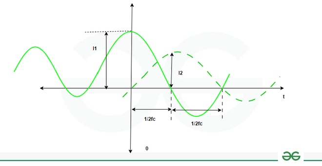
Channel Bandwidth Representation
Pulse Amplitude Modulation Block Diagram
Given below is the Pulse Amplitude Modulation Block Diagram
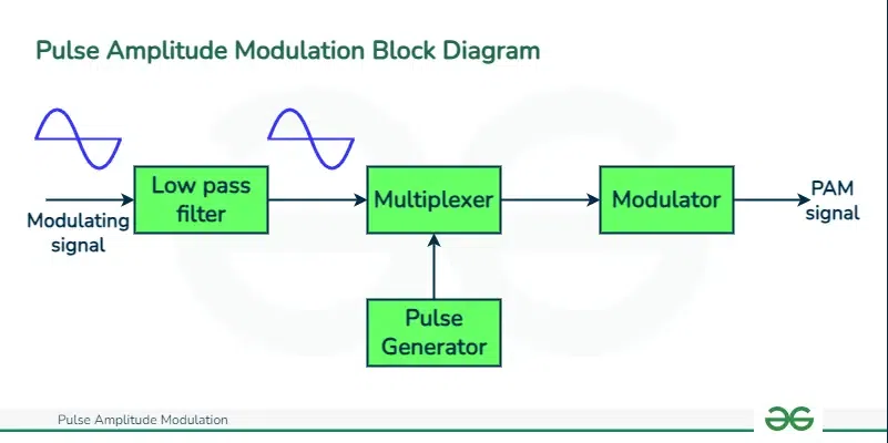
PAM Block Diagram
Working Principle of Pulse Amplitude Modulation (PAM)
Pulse Amplitude Modulation (PAM) is a modulation technique where the amplitude of a series of pulses is varied according to the amplitude of the analog signal being transmitted.
Steps involved in Pulse Width Modulation are as follows :
With pulse amplitude modulation (PAM), the amplitude of a sequence of pulses is changed in response to the amplitude of the analog signal that is being sent. Here’s a detailed breakdown of how PAM functions:
- Sampled: Periodically the analog signals are sampled. These are called sampling intervals, and an aliasing of these has no chance if we put a condition for the sampling rate, “Nyquist theorem” states that the sampling frequency must at least be twice the highest frequency component of the signal.
- Quantization: Each sample is provided with quantized amplitude. The resolution of the system is what contributes to the quantization level. For illustration, an 8−bit system has the number of possible levels being 2^8 = 256. The process of quantization speaker rounding the title of frequencies or the frequencies of alongside that are adjacent to one another is in order to reduce the loss of bandwidth and wastage of valuable information from the message signal.
- Modulation: Since each sample’s quantization level constitutes the amplitude of the generated pulses, only single pulses are produced if every sample level is integer. Often, the pulse doesn’t change its width, but its amplitude can adopt any of the quantified sample values.
- Transmission through the medium of transmission: The carrier, for example, is a visual analog signal or digital one is represented as the pulse train that is modulated. It can be transmitted through wireless or wired pathway depending on the framework of purpose that lies behind it.
- Reception: The reception results in amplitudes modulation which then undergoes a process of demodulation. Firstly, the firm needs to isolate the pulse and get the pulses strength which are represented by their amplitudes.
- Reconstruction: By the summation of different orders of the magnitudes outlined in a given position, the low frequencies are under modulated and the final rebuild into a continuous signal. This also means that it is used for the interpolation.
- Pass-through filtering: The degree of conversion of PAM is higher than that of PDM because the latter including the high-frequency components in its pulse train generation process. A low-pass filter is generally employed to take out the high-frequency components from the smooth recovered analog signal, which meanwhile preserves the original analog signal component.
Types of Pulse Amplitude Modulation
Given below are the Types of Pulse Amplitude Modulation

Types of Pulse Amplitude Modulation
- Single-Pulse Amplitude Modulation (SPAM) –One pulse is used to represent each symbol in SPAM. This pulse’s amplitude varies based on the incoming signal. Generally, each pulse’s duration matches the period of a symbol.
- Double-Pulse Amplitude Modulation (DPAM)- DPAM is an advanced variant of PAM in which two pulses are used to represent each symbol. There is a specific amount of time between these pulses. Each pulse in the pair has its amplitude altered to reflect various amplitude levels. When it involves strength against channel limitations and noise performance, DPAM is preferable over SPAM.
Types of Sampling Techniques
There are two types of sampling techniques :
- Flat Top PAM
- Natural PAM
Flat Top PAM
With a rectangular pulse of a defined size and duration applied across channels, the Flat Top PAM (pulse amplitude modulation) technique does the whole job perfectly. To achieve successful implementation of both transverse sampling and the required frequency range, each pulse carries the coded sample value.
The flat top pulse of the PAM builds the constancy in the signal’s amplitude over the pulse of duration that in turn makes this signal suitable for telecommunication applications.

Flat Top PAM Waveform
Natural PAM
Pulse amplitude modulation, that naturally does not have shaping technique is the Natural PAM. It is not an encoding but uses the waves peaks of the nature. In demodulation, the samples individual amplitude are equal to the peak amplitude of a segment of the wave, which makes demodulation. It has the weakness of distortion and noise although its form is very simple. It appears with a multiple utilize case as simple bit transmission and/or low-cost data solutions, where the highly accurate signal retrieval is not required and the system complexity must be excluded.

Natural PAM
Mathematical Expression for Pulse Amplitude Modulation
A modulation method used in signal processing and telecommunications is pulse amplitude modulation, or PAM. It involves modulating the amplitude of a sequence of pulses in accordance with the modulating signal’s amplitude.
A periodic train of signals is the unmodulated carrier signal in pulse modulation. Thus, the following is a description of the pulse train.
up(t)=[Tex]\sum_{K=-\infty}^{\infty} A rect \frac{t-KTs}{\tau}[/Tex]
The unmodulated pulse amplitude is represented by the letter “A” in the pulse train.
τ stands for pulse width.
“Ts” is a symbol for the periodic time of the pulse trains.
The modulating signal in PAM allows for the modification of the signal amplitudes. Here, the modulating signal, such as m(t), PAM, can be obtained by multiplying the modulating signal by the carrier signal. The output is a collection of pulses that can have their signal amplitudes adjusted using the modulating signal.
The pulse train’s periodic time is called the sampling period.
Fs = 1/Ts
This is an explanation of the equation for natural pulse amplitude modulation:
[Tex]up(t)=a_0+\sum_{n=1}^{Z}a_n cos \frac{2 \pi nt}{T_s}[/Tex]
[Tex]=a_0+a_1cos\frac{2 \pi nt}{Ts}+a_2cos \frac{4 \pi nt}{Ts}+…[/Tex]
The modulated pulse train can be described like
E(t) = m(t) +Up(t)
= a0 m(t) + a1 m(t) cos2πnt/Ts + a2 m(t) cos4πnt/Ts+….
Construction of Pulse Amplitude Modulation
An amplitude modulation circuit, a carrier signal source, and a pulse generator can be used in a simple arrangement to generate a Pulse Amplitude Modulation (PAM) signal.
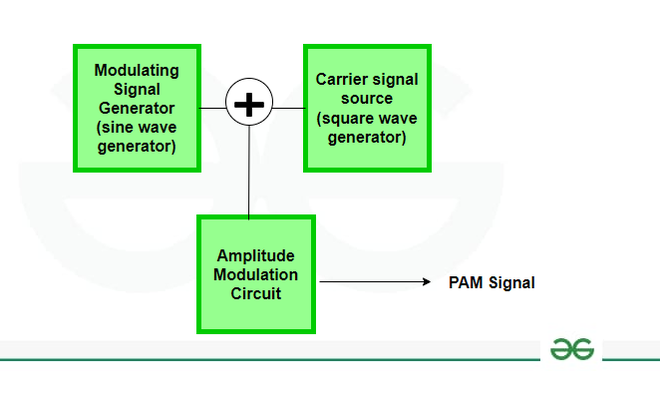
Block Diagram for PAM Generation
- The signal that modifies the carrier signal’s amplitude is produced by the modulating signal generator. Depending on the application, this signal might include any desirable waveform (sine, square, etc.).
- Carrier signal source produces the carrier signal. This signal is usually a high-frequency waveform, most frequently a sine wave.
- The PAM signal is created by this circuit by combining the modulating and carrier signals. The carrier signal’s amplitude is managed by the modulating signal.
Pulse Amplitude Modulation Circuit
Here, we will discuss the Circuit diagram of Pulse Amplitude Modulation given below :

PAM Circuit Diagram
- The signal that contains the data you desire to send is generated by the modulating signal generator.
- The high-frequency waveform that the carrier signal is composed of, is produced by the carrier signal source. Typically, this signal has a frequency that is substantially higher than the modulating signal.
- The carrier signal and the modulating signal are combined in the amplitude modulation circuit. Usually, a multiplier circuit such as a transistor circuit or an integrated circuit intended for modulation is used for this. The carrier signal’s amplitude is managed by the modulating signal. The carrier signal’s amplitude is modulated in accordance with variations in the amplitude of the modulating signal.
- The PAM signal is the result of the amplitude modulation circuit. The modulating signal affects the amplitudes of the pulses in this signal.
Pulse Amplitude DeModulation Block Diagram
Here, we will discuss the block diagram of Pulse Amplitude Modulation with respect to Demodulation :
Demodulation of PAM Signal
Extracting the original data from the modulated signal is the demodulation process of pulse amplitude modulation, or PAM. Typical methods include matched filtering, which compares the received signal with a reference pulse shape; envelope detection, which extracts the envelope of the signal using low-pass filtering; sample expression that samples a signal at symbol rate and compares it to threshold values; decision feedback, which combines sampling with feedback from previously observed symbols.

Block Diagram for PAM signal Demodulation
Solved Examples on PAM
Consider a sinusoidal modulating signal with amplitude 2V and frequency 1 kHz. Modulate this signal onto a carrier signal with amplitude 10V and frequency 10 kHz.
We know that equation for PAM signal :
s(t)=(A c +A m ⋅sin(2πf m t))⋅sin(2πf c t)
Substituting the given values:
s(t)=(10V+2V⋅sin(2π×1000×t))⋅sin(2π×10000×t)
The PAM signal, or carrier signal modulated by sinusoidal modulating signal, is represented by the above equation. The modulating signal’s amplitude affects the carrier signal’s amplitude. There are changes in the carrier’s amplitude at the modulating signal’s frequency because the carrier signal’s frequency is significantly greater than the modulating signal’s.
Consider a modulating signal with amplitude varying between -3V and +3V and a carrier signal with an amplitude of 5V. Modulate the carrier signal using PAM.
Equation for PAM signal is: s(t)=(Ac+Am(t))⋅c(t)
When the modulating signal is at +3V, the PAM signal will be at its maximum:
s(t)= 5V+3V=8V
When the modulating signal is at -3V, the PAM signal will be at its minimum:
s(t)= 5V – 3V= 2V
So, the PAM signal will vary between 2V and 8V, depending on the modulating signal.
Applications of Pulse Amplitude Modulation
- To send digital data over phone lines, digital subscriber line (DSL) modems use PAM.
- Pulse code modulation is used in audio CDs to encode analog audio signals into digital form.
- Digital data is sent across optical fibers using PAM in fiber optic communications.
- Physiological signals are sent over PAM in biomedical signal processing, including electrocardiography (ECG).
- Pulse width modulation (PWM) techniques are used in PAM-based industrial automation systems to control motor speed and position.
Advantages of Pulse Amplitude Modulation
- PAM is inexpensive and simple to integrate into a variety of systems because it only requires simple analog circuitry.
- It facilitates the transfer of analog information via digital communication channels without compromising quality by encoding analog signals with discrete amplitude levels.
- PAM transmits analog signals over digital communication networks with ease, making it compatible with contemporary digital communication protocols. This is made possible by its integration with digital systems.
- PAM is simple, it has strong noise immunity and can withstand noise interference both during signal transmission and reception.
- Simple signal processing methods like filtering and demodulation are made possible by PAM, which makes it possible to efficiently extract information from modulated signals for a variety of applications, such as audio transmission and telecommunications.
Disadvantages of Pulse Amplitude Modulation
- PAM is susceptible to amplitude changes, which can reduce signal quality and causes information loss during transmission, particularly when noise or channel distortion is present.
- Compared to other modulation techniques, PAM demands a large bandwidth, which results in lower efficiency in accordance with limited bandwidth and lowers the total capacity for data transmission.
- PAM has a reduced SNR, especially in high-noise settings where background noise can obstruct the signal and reduces the accuracy and dependability of the data being sent.
- PAM signal demodulation demands exact time recovery and synchronization procedures, which can be difficult and computationally expensive.
- Especially in overcrowded frequency spectra or difficult electromagnetic environments, PAM signals are susceptible to interference from other signals or electromagnetic sources, which could result in possible signal distortion.
Conclusion
An easy-to-use and efficient way to transmit analog data over digital communication channels is pulse amplitude modulation, or PAM. Despite the advantages of simplicity, compatibility with digital systems, and flexibility in signal processing, PAM has disadvantages such as noise sensitivity, poor bandwidth utilization, and complex demodulation. Although it is widely used in business automation, voice and data communication, its limitations make the design and implementation very special. In general, PAM is still the basic modulation method, but innovations in signal processing and modulation systems eliminate its shortcomings and provide reliable and efficient data exchange.
Pulse Amplitude Modulation – FAQs
What factors affect pulse amplitude modulation?
The amplitude of the pulse carrier varies in the pulse amplitude modulation, or PAM, approach and is proportional to the instantaneous amplitude of the message signal.
What is Aperture effect in pulse amplitude Modulation?
When the sample window width during demodulation might result in distortion or mistakes in the recovered signal, this is known as the aperture effect in pulse amplitude modulation, or PAM. When the sampling rate is low or the modulation frequency is high, this impact is more apparent. Precise time-based synchronization, suitable demodulation methods, and sampling window width optimization are essential to mitigate this.
How is PAM different from PWM and PPM?
Pulse Width Modulation (PWM) varies the width of pulses, Pulse Position Modulation (PPM) varies the position of pulses, while PAM varies the amplitude of pulses.
Share your thoughts in the comments
Please Login to comment...