Imagine yourself as a kid who wishes to play with a toy car that runs on batteries. You want to play for long and so you want the batteries to last as long as possible. The “Power Triangle” can help you achieve this. The Power Triangle shows what percent of the battery’s power is being used to move the car in the forward direction and what percent of the battery’s power is being used to rotate the motor, or in particular terms the Active Power (P), Reactive Power (Q) and the Real(or Apparent) Power (S). You can use the Power Triangle to reduce the power consumption so that the batteries last longer and you can enjoy much.
In this article we will be going Through What this is the Power triangle, In this, we will go through the Power Factor(Leading as Well as Lagging), then we will go through the Power Triangle of Ac, In this we will go through Active, Reactive and Apparent power in depth. At last, we will conclude our Article with Solved Problems, Its Application with its Advantages and Disadvantages.
What is a Power Triangle?
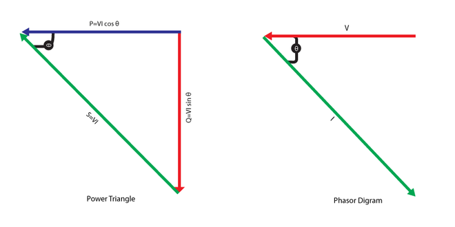
The power triangle is a right-angle triangle where Hypotenuse is the apparent power or true power (S), the Opposite side is the reactive power (Q) and the leftover Adjacent side is the active power or real power (P). These three parameters of AC circuits follow the Pythagoras’ theorem as S2 =P2+Q2. The angle between P and S gives the Power Factor (or cos θ ).
.png)
Power Triangle
There are two primary types of Power Triangle:
- Leading Power Factor
- Lagging Power Factor
Power Factor
The angle θ in the Power Triangle given above is called the power factor angle as its cosine that is cos θ gives us Power Factor .Its a dimensionless quantity as its the ratio of average power to the apparent power .In other terms , the power factor is the cosine of the phase difference between voltage and current , its the cosine of the angle of the load impedance.
Power Factor Can be Written as
[Tex]Power Factor Cos\theta=\frac{Active Power}{Apparent Power}=\frac{KW}{KVA}
[/Tex]
-660.png)
Power Analysis in AC circuits
Power Factor= P/S=cos θ=cos( θv-θi )
v(t)=Vmcos( wt + θv ) & i(t)=Imcos( wt+θi ) or in phasor form, V=Vm∠θv & I=Im∠θi Vrms=(V/√2) & Irms= (I/√2)Apparent Power ( S in VA ) =√( P2 +Q2 ) VrmsIrms=(V/√2)(I/√2)=0.5VmIm = VrmsIrms∠( θv -θi ) = VrmsIrmscos( θv -θi ) + jVrmsIrmssin( θv -θi ) = P + jQ = SReactive Power ( Q in VAR) = VrmsIrmssin( θv -θi ) Real Power ( P in W ) = 0.5VmImcos( θv -θi ) = S cos( θv -θi )
Note:
- Q=0 for resistive loads ( unity power factor )
- Q<0 for capacitive loads ( leading power factor )
- Q>0 for inductive loads ( lagging power factor )
Leading Power Factor
When the load is largely capacitive, leading power factor arises, resulting in a phase angle (θ) of less than 90 degrees between P and S.
-660.png)
Leading Power Factor
Lagging Power Factor
When the load is largely inductive, lagging power factor happens, resulting in a phase angle (θ) of greater than 90 degrees between P and S.
Lagging Power Factor
Power Triangle of AC circuits
In AC Circuits there are three types of power
- Apparent power (S)
- Active power (P)
- Reactive power (Q)
Let , V= R.M.S. value of applied Voltage , I= R.M.S. value of current flowing in AC circuit and θ = angle between voltage V and current I ( = θv-θi )
Apparent Power (S)
It is the product of the R.M.S. value of the applied voltage and circuit current. It is also known as wattless or idle power .
S= V.I ( Volt-Ampere or VA )
Active Power (P)
It is the power which is developed in the circuit resistance.
P=V.I.cos θ = V.I. ( R/Z ) ( Watt ) = (V/Z) .I.R = I.I.R = I2R
Reactive Power (Q)
It is the power which is developed in the circuit reactance.
Q=V.I.sin θ =V.I.( X/Z) ( Volt-Ampere-Reactive or VAR ) = (V/Z) .I.X =I.I.X= I2X
There is a relation between S,P and Q .
P2 + Q2 = (V.I.cos θ)2 + (V.I.sin θ )2 [ cos2 θ+sin2 θ = 1 ] = ( V.I )2 = S2 Therefore, P2 + Q2=S2 and S= √ ( P2 + Q2 )
Impedance ( Z ) is basically resistance of AC circuits and XLand Xc is called inductive reactance and capacitive reactance which is the resistance offered by Inductors and Capacitors individually .
Inductive Reactance ( XL )=2πfL Capacitive Reactance ( XC )=2πfC Impedance ( Z ) = √ (R2 +( XL - XC )2)Here XL <0 and XC>0

Power Triangle [ S = P + jQ ]
.png)
Impedance Triangle[ Z = R+ jX ]
Z= √ (R2 +( XL - XC )2) = V/I=Vrms/Irms=Vrms/Irms ∠( θv -θi ) I=V/ZS = I2rms ZP=I2rmsRQ=I2rms X
Power Factor of AC circuits
Power Factor , cos θ , is an essential component of an AC circuit . It is defined as the ratio of real power (P) to apparent power (S) which is generally a decimal value .It lies in the range 0 to 1 , for example 0.95 or 95%.It also defines the phase angle between V and I
Power Factor = P/S= VI cos θ /VI = cos θ
Power Factor ( cos θ )
Evolution of Power Triangle
The Power Triangle is a tool that that gives information about variables P,S,Q and cos θ or Power Factor. The power triangle can be seen as an analogy for evolution. A high power factor is analogous to a well adapted organism that is the circuit is working fruitfully to do useful work and vice versa applies .Evolution is a process of adaptation, similarly the power triangle is a process of optimization and maximizing active power and minimizing reactive power . As evolution of living organisms is a continuous process , new technologies and different ways for power optimization are being developed using the Power Triangle .
Effects
Effect
| Low Power Factor
| High Power Factor
|
|---|
Energy Loss
| Increases
| Decreases
|
Equipment overheating
| Increases
| Decreases
|
Power quality
| Decreases
| Increases
|
Voltage drop
| Increases
| Decreases
|
High Power Factor is anyways better than Low Power Factor as it cuts down energy costs , increased lifespan of the device with greater reliability .To improve the Power Factor , use correction devices such as capacitors , reactors and filters , avoid circuit overloading and do regular maintenance .
Working of Power Triangle
The Power Triangle works by calculating the power factor (cosθ) using the relationship between P, Q, and S. It is basically a right angle triangle that follows the Pythagoras’ theorem .Mathematically we can conclude the two points as follows:
- Power Factor (cos θ) = P/S
- S2 =P2+Q2
Properties of Power Triangle
The Power Triangle exhibits the following properties:
- Power factor (cos θ) is always a value between 0 and 1 .
- A circuit exhibiting a leading power factor is considered capacitive where θ <90 degree , whereas a circuit exhibiting lagging power factor is considered inductive where θ >90 degree .
Characteristics of Power Triangle
Key characteristics of the Power Triangle include:
- It provides data for the variables P,Q,S and Power Factor (or cos θ ) .
- It aids in energy usage optimization and power factor adjustment.
- It helps in making electronic circuit design better and more optimized.
Applications of Power Triangle
The power triangle is used to analyze and improve the efficiency, reliability, and power quality of electrical systems in a variety of real-life applications , to say a few – improving the efficiency of electric motors , improving performance of electronic circuits , reducing electricity bills and many more .Its main application is to cut on cost and get more output in less time .
Advantages and Disadvantages of Power Triangle
Some of the advantages and disadvantages of Power Triangle are :
Advantages of Power Triangle
- Lower energy expenses are the result of an improved power factor or high power factor.
- Improved system performance and lower power losses.
Disadvantages of Power Triangle
- The application of power factor correction methods could result in extra expenses.
- This is a traditional method that has become old now with newer innovations coming up .
Power Factor Improvement
The process of increasing power factor without altering the voltage or current to the original load is known as power factor correction. Since most loads are inductive , power factor can be improved by installing a capacitor in parallel with the load .The effect of this can be understood with the Power Triangle or the Phasor Diagram .By choosing a suitable size of capacitor , the current can be made to be completely in phase with the voltage , implying unity power factor.
Comparison between Leading & Lagging Power Factor
Characteristic
| Leading Power Factor
| Lagging Power Factor
|
|---|
Definition
| Current leads the voltage
| Current lags the voltage
|
Cause
| Inductive loads
| Capacitive loads
|
Effect on power factor
| Increases power factor
| Decreases power factor
|
Correction
| Use capacitors
| Use inductors
|
Solved Problems
Problem 1: A circuit has a real power (P) of 2000 W and an apparent power (S) of 2500 VA. Calculate the power factor ( cos θ ).
Power Factor (cos θ ) =P/S=2000/2500=0.8 The power factor is 0.8, indicating an 80% efficiency in power usage.
Problem 2: An inductive load has a real power (P) of 300 W and a reactive power (Q) of 400 var. Calculate the apparent power (S) and the power factor (cosθ).
Using the Pythagorean theorem: S2 =P2+Q2 =9000+160000=250000 => S=500 VAPower Factor ( cos θ )=P/S=300/500=0.6 , The apparent power is 500 VA, and the power factor is 0.6.
Conclusion
Power Factor is the cosine of the phase difference between voltage and current or in other terms its the cosine of the angle of the load impedance or the ratio of real power ( P ) to the apparent power ( S ) . The power factor is lagging if the current lags voltage (inductive load) and the power factor is leading when the current leads voltage ( capacitive load ). The parameters P,Q and S is expressed as P=S cos( θv- θi) , S= VrmsIrms and Q=VrmsIrms sin( θv- θi) where P is calculated in Watts( W ) , Q in VAR and S in VA. The total complex power in a circuit is the sum of the complex powers of all the individual components and the same goes for the total reactive power and total real power, but the apparent power isn’t calculated in the same process. Coming on to the improvement of the power factor , its very important for economic reasons . In short power factor is the game changer of any electrical circuit / device and its very important to consider it while designing . It reduces costs and provides longer shelf life to the electrical devices .
FAQs on Power Triangle
What is the significance of the power factor in the Power Triangle?
The efficiency of power utilization in electrical circuits is shown by the power factor (cos). It assists engineers in identifying power waste and optimizing energy use by measuring the ratio of real power to apparent power.
How can I improve the power factor in a lagging power factor scenario?
In a situation when the power factor is lagging, power factor correction methods like adding capacitors can be utilized to raise the power factor. By lowering the reactive power component, these methods enable more effective use of electrical power.
What are the practical implications of the Power Triangle for consumers?
Understanding the Power Triangle can aid consumers in saving money on energy expenditures and extending the life of electrical equipment. They can use it to make well-informed judgments about energy-saving appliances and power factor correction.
Share your thoughts in the comments
Please Login to comment...