Implementation of OR Gate from NOR Gate
Last Updated :
25 Apr, 2024
The Logic gates are the Fundamental Building Blocks of the Digital Circuits. The Logic Gate takes one or more Binary inputs and performs logical Operations to Produce a single binary Output. Understanding through the Different Combinations of gates is important for the Designer to produce the desired functionality in digital circuits. By Understanding the properties and behaviour of different logic gates and their combinations, the designer can design and optimize the digital circuit as per the requirement.
In this Article, We will be going through the Implementation of the OR Gate from the NOR Gate. It is one of the Important Concepts in Digital Electronics. We will start our Article With a Brief description of Both the gate and go through its truth table and the diagram. Then, We will go through all the basics of both gates. Then we will see the logic of how to implement the or gate from the nor gate in depth.
What is an OR Gate?
The OR gate is one of the Fundamental and Basic Logic gates in digital electronics. The OR gate is represented by the plus Sign(+). The Nor gate can take two or more inputs according to the requirement. In this gate if any of its inputs are true then the output will also be True. The OR gates are used in combination with other gates to implement various logical Expressions and operations in the Digital circuit.
Types of OR Gate
OR Gate are of Two Types
- 2 Input OR Gate
- 3 Inputs OR Multi-Input
2 Input OR Gate
2 Input OR gate are most common and Simplest type of OR Gate. In this gate two inputs are Provided and Single Output is Obtained. The output will be true if either or both the inputs are true. Given Below is the diagram and Equation of the 2 Input Or gate.
X=(A+B)
Where is the X is the Output and A and B are the inputs Provided

2 Input OR gate
3 Inputs or Multi Input OR Gate
This gate will take three or more than three inputs and Produce a single output. The output of this gate is true if at least one of its inputs are true. Given Below is the diagram and Equation of the 3 Input Or gate.
X=(A+B+C)
Where is the X is the Output and A,B and C are the inputs Provided

3 Input Or gate
What is a NOR Gate ?
Nor Gate is the another Fundamental and Universal gate in the Digital Electronics. The Nor gate is Represented by OR gate symbol with the added small circle at the output. The output of the Nor gate is true only when all of its inputs are false and When any one of the Inputs are true then the output will be false. The NOR gates are used in combination with other gates to implement various logical Expressions and operations in the Digital circuit and in this Article we will go through how it can be implemented.
Types of NOR Gate
Nor gates are of Two Types
- 2 Input NOR Gate
- 3 Inputs or Multi-Input
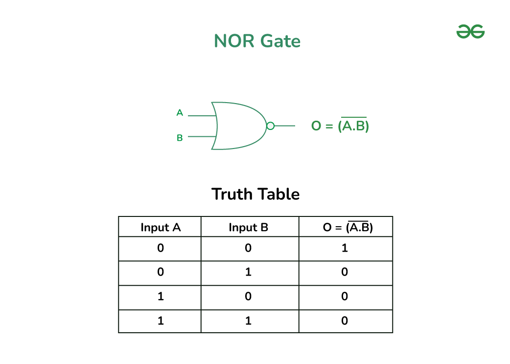
2 Input NOR Gate
It is simples and the basic NOR Gate. It takes Two inputs and Provides a single output. If both the inputs are false then the output will be true and false if any of the input is true. Given Below is the diagram and Equation of the 2 Input NOR Gate.
O=
where O is the Output and A and B is the Input given
2 Input NOR Gate
3 Inputs or Multi Input NOR Gate
It will take three or more than three inputs and Produce a single output. The output of this gate is true if all the inputs are false and false when any of the Inputs are true. Given Below is the diagram and Equation of 3 Inputs or Multi Input Nor Gate
O=
Where O is the Output and A,B and C is the Input given

3 Input NOR Gate
Implementation of OR Gate from NOR Gate
After going through the Both gate, Now we will Discuss How to Implement the OR gate using the NOR. Given Below is the Connection Diagram and Explanation of the Implementation.

Implementation of OR Gate from NOR Gate
- Let A and B are the input given in the NOR gate(a), then the output Y will be Y=
 .
. - The Output of the OR gate is A+B. To Obtain this A+B from the Output Y=, we will use another NOR gate Which will take Y as Both the Input.
- Now the Output Obtain from the NOR gate(b) will be Z =
 using De-morgan’s law Z will be Written as Z=A+B which is the Equation for the OR gate.
So, This how we can Implement the OR gate using the NOR Gate.
Conclusion
In this Article, we have gone Through the Concept of both the fundamental gates in the digital electronics. We have Examined the Basic Principles, types, Truth Tables and their Symbolic Representation. Furthermore we have gone through the the implementation of the OR gate using the Nor gate, Showing how the logical operations can be done to provide the desired functionality. Through this Article we have understand the logical gates and their Combination which is Crucial for a designers to Achieve the Specific Logic Requirements.
Implementation of OR Gate from NOR Gate – FAQs
Why is the OR gate considered fundamental in digital electronics?
The OR gate is fundamental because it represents a basic logical operation that is used in digital circuits. It allows designers to combine multiple input or conditions, making it Important for implementing various logical expressions and operations.
What is the significance of understanding logic gates and their combinations?
Understanding the Logic gate and their Combinations are Important as without the Knowledge about it the designers cannot design and optimize the digital Circuit as per their Requirements.
What are some applications of logic gates in real-world scenarios?
Logic gates are used in many electronic devices and systems, including computers, calculators, digital signal processors, and communication systems. They are Important for processing and manipulating digital data.
Share your thoughts in the comments
Please Login to comment...