The flow of charged particles is referred to as electrical current. In current electricity, the charge flow would be continuous. A current of electricity travels from a higher to a lower electric potential.
A circuit consisting of a closed-loop of conducting material is required for current to flow. The circuit is made up of wires that are connected end to end and move in the same direction.
When a stream of electrons moves through a conductor it constitutes an electric current. Conventionally it is stated that the direction of current (I) is always taken opposite to the direction of flow of electrons or charge.
Resistance
A physicist Georg Simon Ohm found out the relation between the flowing current I, which is flowing in a metallic wire having the potential difference across its terminals (ends). He stated that: The potential difference in volts V, across the terminals of a given metallic wire in an electric circuit is directly proportional to the current flowing I through it, given its temperature remains the same.
This is known as Ohm’s law. In other words, it can be written as: Potential difference across the ends ∝ Current
or
V ∝ I
V = I R, where R is constant of proportionality called Resistance.
Resistance is a property that opposes (resists) the flow of current, or it can be said that the flow of electrons in a conductor. It controls the magnitude (value) of the current flowing through the circuit.
The SI unit of resistance is measured in ohm, which is denoted by Ω.
Mathematically, Resistance can be defined as:
R = V / I
Here I is the current and V is the potential difference.
- Current is inversely proportional to Resistance. Hence, the greater the flow of current lesser will be the resistance and vice-versa.
- Resistance devices like a rheostat or a variable resistor allow changing of resistance in a circuit keeping the potential difference the same across the ends.
- In a conductor, electrons are attracted by the conductor’s atoms. There is a resistive force that is lower for a good conductor (metals like iron, copper) but very high for an insulator(things like wood, clothes, slippers). The conductor having some resistance in it is known as a Resistor.
Ohm’s Law experiment
As Ohm’s law states: The potential difference across the ends of a resistor is directly proportional to the current through it, provided its temperature remains the same.
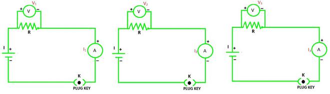
For the same resistance R, when three different voltage sources are taken, the resulting potential difference will always be proportional to the current flowing through the circuit. This implies that:
V1 ∝ I1,
V2 ∝ I2, and
V3 ∝ I3
Result:
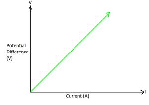
V–I graph for a nichrome wire.
Factors on which Resistance depends
Resistance of a conductor depends on:
- Its length (l),
- Its area of cross-section (A) and
- The nature of its material.
The resistance of the uniformly distributed metallic conductor is directly proportional to its length and inversely proportional to the area of its cross-section.
Therefore, R ∝ l and R ∝ 1/A.
⇒ R ∝ l / A
or
⇒ R = ρl / A
where ρ is the constant of proportionality known as electrical resistivity of the conductor material.
- The SI unit is Ω.m.
- Resistivity varies with temperature (T).
- The value of resistivity of conductors is very low whereas the insulators have very high resistivity.
- Alloys having higher resistivity than metals are used in electrical heating devices, like iron and toasters, copper and aluminum are used for electrical transmission lines, and tungsten is used in filament of electric bulbs.
- Hence, Resistivity of Insulators > Resistivity of Alloys > Resistivity of Conductors.
Combination of Resistors
Resistors are used in various combinations. There are two methods of arranging the resistors in different combinations:
(i) Resistors in Series
(ii) Resistors in Parallel
Equivalent Resistance: The equivalent resistance of combinations of resistors in series is equal to the sum of their individual resistances in the circuit.
Resistors in Series Combination:
Two or more resistances are said to be connected in series when they are connected end to end and the same current flows through each of them in turn. In this case, the equivalent or the total resistance equals the sum of the number of individual resistances present in the series combination.
Mathematically, the equivalent resistance of any number of resistances (R1, R2, R3, R4, R5, ……..) connected in series is given as:
Req = R1 + R2 + R3 + R4 + R5 + ……..
Consider a case of three resistances (R1, R2, and R3) connected in series with each other with the corresponding voltage source (V1, V2, and V3) in a circuit shown below:
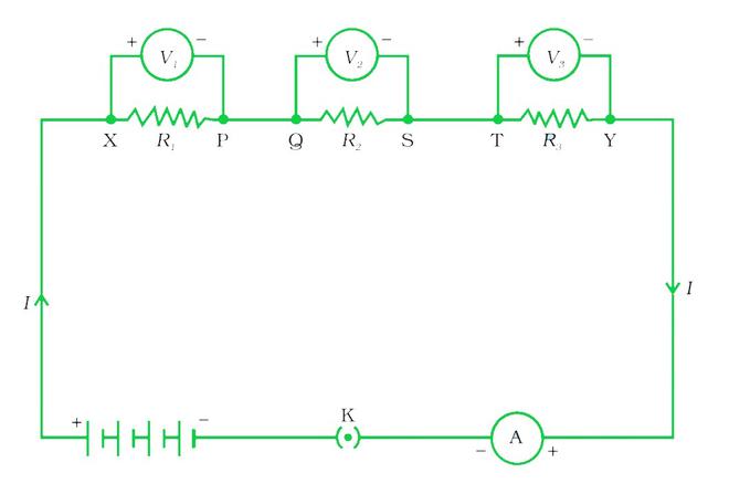
Resistors in Series
The equivalent current flow through it is I, detected through the ammeter A and key K.
The equivalent potential difference is equal to the sum of the individual potential difference across each resistor, i.e.
Veq = V1 + V2 + V3
The current I through each resistor is the same i.e. I = I1 = I2 = I3
Replace the three resistors connected in series by an equivalent single resistor of resistance Req, such that the potential difference Veq across its terminals, and the current I through the circuit remains the same.
Applying Ohm’s law to the circuit:
Veq = IReq
By applying Ohm’s law to all resistors individually as:
V1 = IR1
V2 = IR2
V3 = IR3
Hence, IR= IR1 + IR2 + IR3
or
Req = R1 + R2 + R3
- The current through the circuit will remain the same here.
- The equivalent potential difference is the sum of the individual potential difference across each resistor.
- As a result, equivalent resistance becomes the sum of individual resistances.
- The only disadvantage of a series combination is that, if any resistor in a series combination is disrupted or a failure occurs, the whole circuit is switched off.
- The series combination is needed to increase the resistance and to divide high potential differences across many resistances.
- Such a combination is used in resistance boxes, decorative lights etc.
Resistors in Parallel Combination:
Two or more resistances are said to be connected in parallel connected when they are connected between two points and each has a different current direction. The current is branched out and recombined as the branches intersect at a common point in such circuits.
Mathematically, the equivalent resistance of any number of resistances (R1, R2, R3, R4, R5, ……..) connected in parallel is given as:
1/Req = 1/R1 + 1/R2 + 1/R3 + 1/R4 + 1/R5 + ……..
Consider a case of three resistances (R1, R2, and R3) connected in parallel with each other with the corresponding voltage source (V1, V2, and V3) in a circuit shown below:
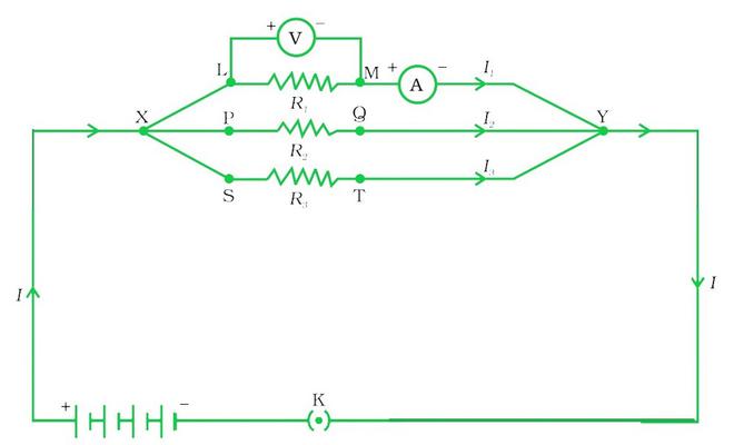
Resistors in Parallel Combination
Here, the current flows through each resistor is different therefore, the equivalent current flown through the circuit is:
Ieq = I1 + I2 + I3
Replace the three resistors connected in parallel by an equivalent single resistor of the parallel combination of resistors be Req.
Now, by applying Ohm’s law to the parallel combination of resistors as:
Ieq = V / Req
On applying Ohm’s law to individual resistors as:
I1 = V / R1
I2 = V / R2
I3 = V / R3
Hence, V / Req = V / R1 + V / R2 + V / R3
or
1 / Req = 1 / R1 + 1 / R2 + 1 / R3
In conclusion, we can say that the reciprocal of the equivalent resistance of a group of resistances joined in parallel is equal to the sum of the reciprocals of the individual resistances.
- The equivalent current through the circuit is the sum of individual currents through each branch of the circuit.
- The potential difference across the two terminal points of the circuit remains the same.
- As a result, the reciprocal of equivalent resistance of the circuit is the sum of reciprocal of the individual resistances.
- In a parallel circuit, a resistor or some other component can be easily connected or disconnected without disturbing the other components.
- In parallel combination, the current flown in the circuit is divided into different branches and hence each component receives the required amount of current.
- Here, the equivalent resistance is always lesser than all the individual resistances.
- If one of the components fails or shorted, the rest of the components of the circuit works usually.
Sample Problems
Problem 1: How much current will an electric lamp draw from a 220 V source, if the resistance of the lamp is 1000 Ω?
Solution:
Given that,
The source voltage, V is 220 V.
The resistance of the lamp, R is 1000 Ω.
The formula to calculate the current drawn is:
I = V / R
Substitute the given values in the above expression as:
I = 220 V / 1000 Ω
= 0.22 A
Hence, the current drawn through the electric lamp is equal to 0.22 A.
Problem 2: If the resistance of the bulb filament is 200 Ω, How much current will an electric bulb draw from a 220 V source?
Solution:
Given that,
The source voltage, V is 220 V.
The resistance of the bulb, R is 200 Ω.
The formula to calculate the current drawn is:
I = V / R
Substitute the given values in the above expression as:
I = 220 V / 200 Ω
= 1.1 A
Hence, the current drawn through the electric bulb is equal to 1.1 A.
Problem 3: The potential difference between the terminals of an electric bulb is 30 V when it draws a current of 6A from the source. What current will the bulb draw if the potential difference is increased to 120 V?
Given that,
The potential difference across the electric bulb, V is 30 V.
The current drawn, I is 6 A.
The increased potential difference, R’ is 120 V.
According to Ohm’s law, the formula to calculate the resistance is:
R = V / I
= 30 V / 6 A
= 5 Ω
When the potential difference is increased to 120 V the current drawn is:
I’ = V / R’
Substitute the given values in the above expression as:
I’ = 120 V / 5 Ω
= 24 A
Hence, the current drawn through the electric bulb is equal to 24 A.
Problem 4: A wire has a resistance of 4 Ω of some given material with length l and cross-section area of A. How much will be the resistance of another wire with the same material having length l/2 and cross-section area of 2A?
Solution:
Consider the resistance of the first wire as:
R1 = ρl / A
where ρ is the resistivity, l is the length and A is the cross-sectional area of the first wire.
But it is given that the resistance, R1 is 4 Ω.
Therefore,
4 Ω = ρl / A ……(1)
Now, in case of second wire:
The length of the wire, l2 is l/2 and
The cross-sectional area, A2 is 2A.
Therefore, the resistance for second wire becomes:
R2 = ρl2 / A2
= ρ(l/2) / (2A)
= ρl / 4A
Substitute 4 Ω for ρl / A, from equation (1) in the above expression.
R2 = 4 Ω / 4
= 1 Ω
Hence, the resistance of the second wire is 1 Ω.
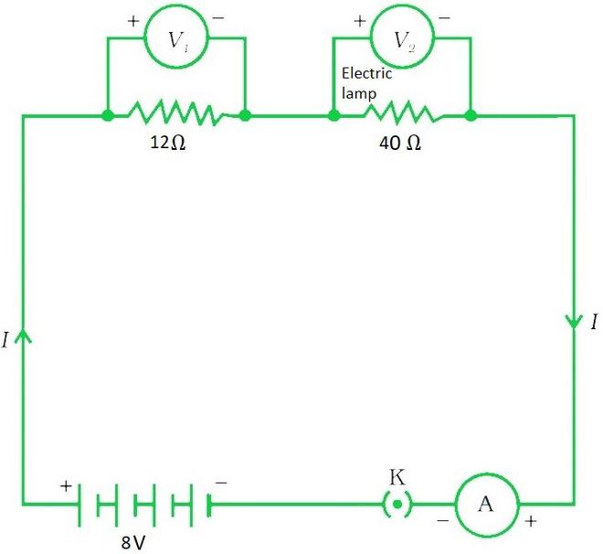
Problem 5: An electric appliance that is connected to a resistance of 40 Ω, and a conductor of 12 Ω resistance to a battery of 8 V in series. Calculate :
(a) Total resistance of the circuit,
(b) Current through the circuit, and
(c) Potential difference across each resistance.
Solution:
The given problem can be represented diagrammatically as:
(a) Given that,
The resistance of electric lamp, R1 = 40 Ω,
The resistance of the conductor connected in series, R2 = 12 Ω.
Therefore, the total resistance of the circuit is:
R = R1 + R2
Substitute the given values in the above expression.
Req = 40 Ω + 12 Ω
= 52 Ω
Hence, the total resistance in the circuit is 52 Ω.
(b) Again, it is given in the problem that,
The total potential difference across the two terminals of the battery, V is 8 V.
Using Ohm’s law, the current flow in the circuit is:
I = V / Req
I = 8 V / 52 Ω
= 0.15 A
Hence, the current through the circuit is 0.15 A
(c) Again, apply Ohm’s law separately to the electric lamp and conductor, the potential difference across the electric lamp is:
V1 = I × R1
= 40 Ω × 0.15 A
= 6 V
And the potential difference across the conductor is,
V2 = I × R2
= 12 Ω × 0.15 A
= 1.8 V
Problem 6: Consider a circuit consist of three resistors as: R1 = 6 Ω, R2 = 18 Ω and R3 = 36 Ω arranged in parallel combination, through a source battery of 12 V. Calculate:
(a) Current through each resistor,
(b) Total current in the circuit, and
(c) Total circuit resistance.
Solution:
The given problem can be represented diagrammatically as:
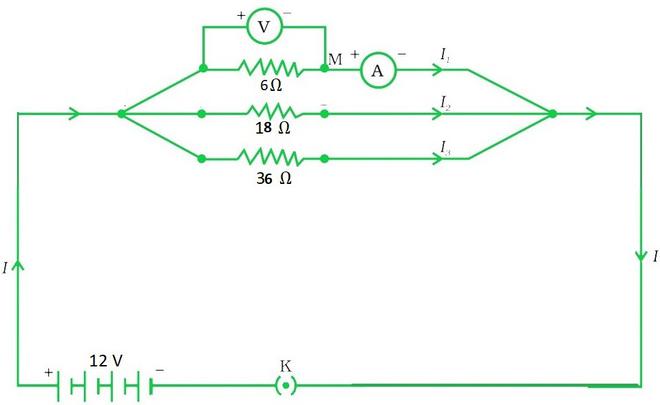
The resistances connected in parallel combination are: R1 = 6 Ω, R2 = 18 Ω, and R3 = 36 Ω.
The potential difference across the battery, V is 12 V.
Since, the circuit has resistors connected in parallel, then the potential difference across the terminals of the individual resistor will be same.
Hence, to calculate the current in the resistors, use Ohm’s law as:
I1 = V / R1
= 12 V / 6 Ω
= 2 A
Similarly,
I2 = V / R2
= 12 V / 18 Ω
= 0.66 A
And
I3 = V / R3
= 12 V / 36 Ω
= 0.33 A
Therefore, the total current in the circuit,
I = I1 + I2 + I3
= (2 + 0.66 + 0.33) A
= 2.99 A
Hence, the current through each resistor is 2 A, 0.66 A and 0.33 A and the total current in the circuit is 2.99 A.
The total resistance Req is:
1 / Req = 1 / R1 + 1 / R2 + 1 / R3
= 1/ 6 Ω + 1/ 18 Ω + 1/ 36 Ω
Req = 4 Ω
Hence, the total circuit resistance is 4 Ω.
Share your thoughts in the comments
Please Login to comment...